
Image scanning system and method and electronic equipment

An image scanning and image scanning device technology, applied in the field of image scanning, can solve the problems of not being able to fully scan, damage paper content, and fail to recognize and read paper, etc., to achieve fully automatic scanning, meet scanning needs, and improve quality and efficiency Effect

Pending Publication Date: 2021-12-17
广东新裕信息科技有限公司
View PDF0 Cites 0 Cited by
  • Summary
  • Abstract
  • Description
  • Claims
  • Application Information

AI Technical Summary

Problems solved by technology

[0002] In the prior art, there are usually two ways to scan images. One is to use a scanner. This kind of scanner is often integrated with a printer, and uses a paper feeding and output method similar to a printer, and scans and prints in a similar way to laser printing. Synthetic image, another way is to manually place the paper on the platform, and then manually remove the paper after scanning, sweeping one piece and taking one away, but the former cannot recognize the specific content on the read paper, and the adjacent There is a large friction between papers. For specific papers, such as watercolors, oil paintings and other paintings, the existing scanning methods will damage the content of the paper, and the latter cannot be scanned automatically, resulting in low quality and low efficiency of the existing image scanning methods. , it is difficult to meet the scanning requirements

Method used


Image

  • Image scanning system and method and electronic equipment
  • Image scanning system and method and electronic equipment
  • Image scanning system and method and electronic equipment

Examples


Embodiment Construction

[0039] Embodiments of the present invention are described in detail below, examples of which are shown in the drawings, wherein the same or similar reference numerals designate the same or similar elements or elements having the same or similar functions throughout. The embodiments described below by referring to the figures are exemplary only for explaining the present invention and should not be construed as limiting the present invention.

[0040] In the description of the present invention, several means more than one, and multiple means more than two. Greater than, less than, exceeding, etc. are understood as not including the original number, and above, below, within, etc. are understood as including the original number. If the description of the first and second is only for the purpose of distinguishing the technical features, it cannot be understood as indicating or implying the relative importance or implicitly indicating the number of the indicated technical features ...


PUM


Abstract

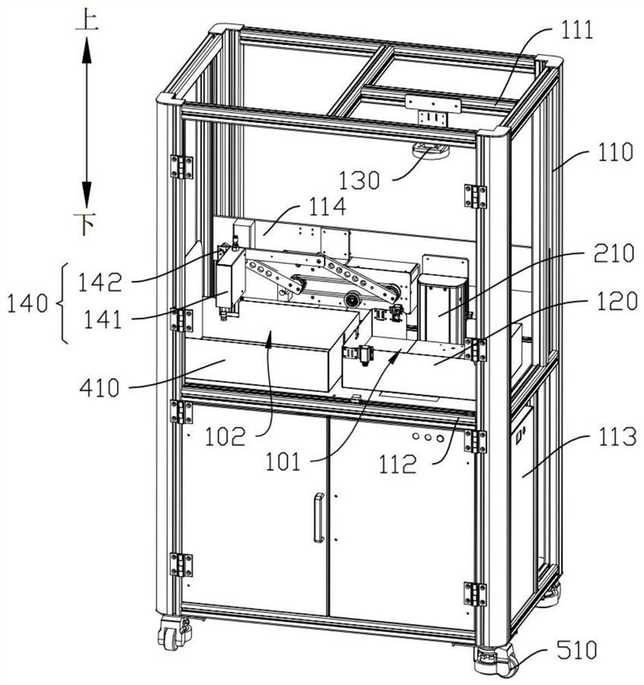
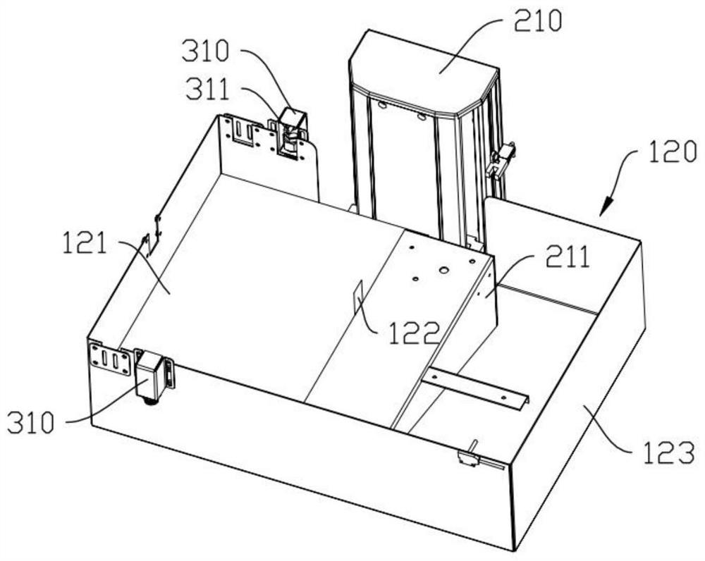
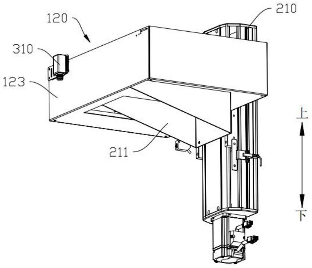
The invention discloses an image scanning system and method and electronic equipment, and the image scanning system comprises: a rack which comprises a first support and a second support, wherein the heights of the first support and the second support are different; a paper taking device, wherein the paper taking device is arranged on the second support, and the paper taking device is used for placing a first drawing so as to enable the first drawing to be located at a first position; an image scanning device, wherein the image scanning device is arranged on the first support, the position of the image scanning device corresponds to the position of the paper taking device, and the image scanning device is used for scanning the first drawing on the first position to obtain image information; and a transferring device, wherein the transferring device comprises a moving assembly and a fixing assembly which are connected with each other, the fixing assembly is installed on the rack, the moving assembly is movably connected to the fixing assembly, the position of the moving assembly corresponds to the position of the paper taking device, a paper taking piece is arranged on the moving assembly, the paper taking piece is used for moving the first drawing from a first position to a second position, and the first position corresponds to the second position.

Description

technical field [0001] The invention relates to the technical field of image scanning, in particular to an image scanning system, method and electronic equipment. Background technique [0002] In the prior art, there are usually two ways to scan images. One is to use a scanner. This kind of scanner is often integrated with a printer, and uses a paper feeding and output method similar to a printer, and scans and prints in a similar way to laser printing. Synthetic image, another way is to manually place the paper on the platform, and then manually remove the paper after scanning, sweeping one piece and taking one away, but the former cannot recognize the specific content on the read paper, and the adjacent There is a large friction between papers. For specific papers, such as watercolors, oil paintings and other paintings, the existing scanning methods will damage the content of the paper, and the latter cannot be scanned automatically, resulting in low quality and low effici...

Claims


Application Information

Patent Timeline
Patent Type & Authority Applications(China)
IPC IPC(8): H04N1/00H04N1/04
CPCH04N1/00562H04N1/0057H04N1/04
Inventor 林锦龙吴炜权
Owner 广东新裕信息科技有限公司
Learn More