Clamp capable of applying pulling/pressing cyclic load to CT test piece

A cyclic load and test piece technology, applied in the direction of applying stable tension/pressure to test the strength of materials, instruments, measuring devices, etc., can solve the problems of load neutrality variation, pin hole micro cracks, small aluminum block movement, etc. Achieve the effect of improving utilization rate, improving clamping efficiency and ensuring load neutrality

Active Publication Date: 2021-12-17
BEIHANG UNIV
View PDF6 Cites 0 Cited by
  • Summary
  • Abstract
  • Description
  • Claims
  • Application Information

AI Technical Summary

Problems solved by technology

[0005] The technology of the present invention solves the problem: the deficiency of the existing fixture is found. When the U-shaped fixture applies a pressure-compression cyclic load, the pin unit may contact the pin hole, causing microcracks and plastic deformation at the pin hole; the process of ballasting prefabricated cracks In the middle, the small aluminum block is likely to move, resulting in poor load centering. Therefore, in view of the problems existing in the existing fixture, the new fixture will simplify the structure and make reasonable improvements

Method used


Image

  • Clamp capable of applying pulling/pressing cyclic load to CT test piece
  • Clamp capable of applying pulling/pressing cyclic load to CT test piece
  • Clamp capable of applying pulling/pressing cyclic load to CT test piece

Examples


Embodiment Construction

[0027] By the following Figure 1-9 And implementation step further illustrates the technical solutions of the present invention.

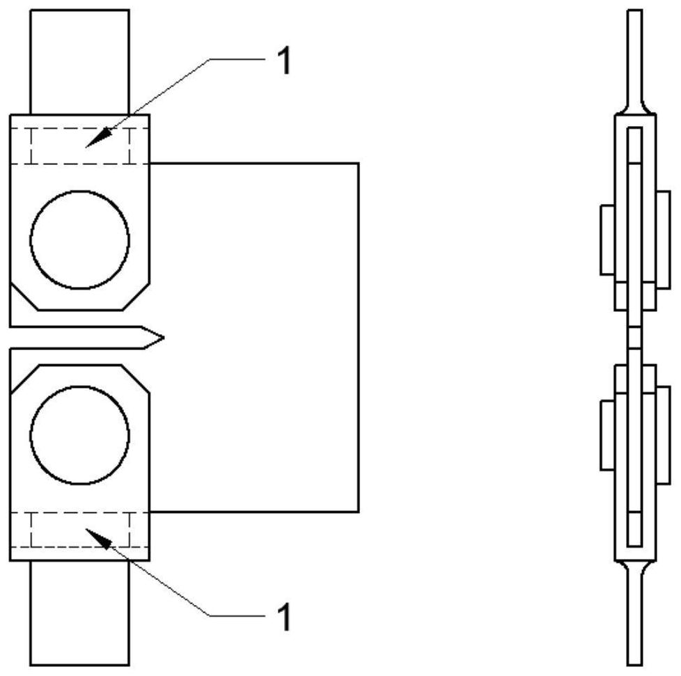
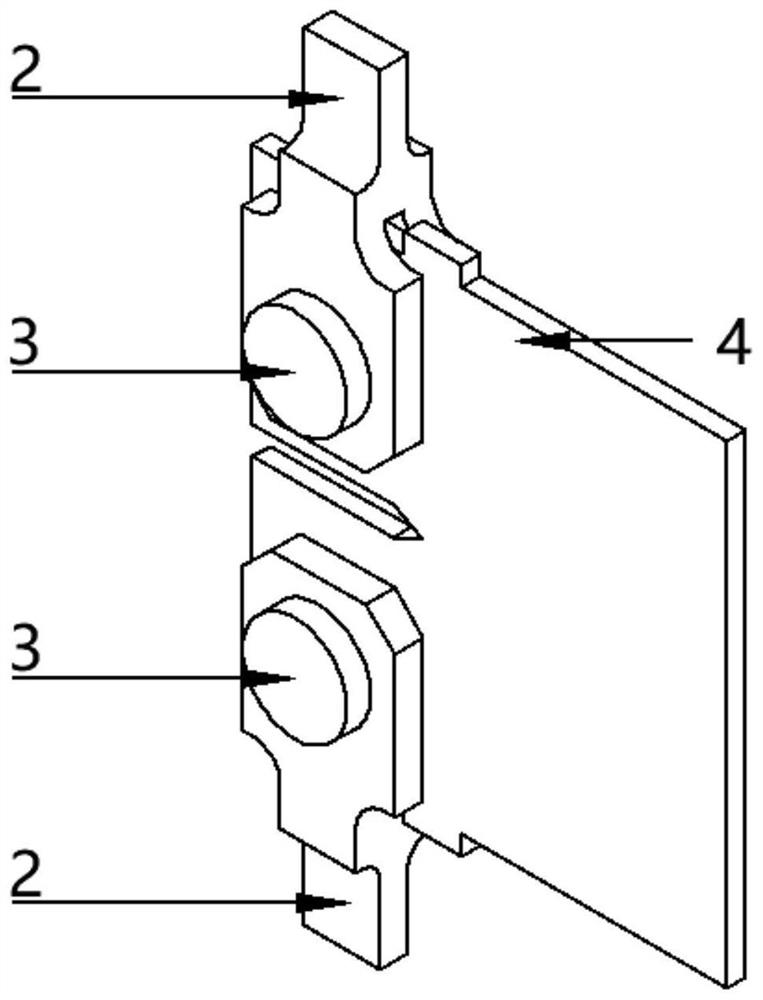
[0028] 1, CT test piece 4 uses 7075 aluminum alloy manufacturing, this test will use small CT test pieces, the detailed structure size of the test piece can be referred to the ASTM-E647 standard, then design fixture according to the CT test piece 4 size;

[0029] 2, press-pressure circulating load prefabricated cracks. The test was carried out on the MTS-880 fatigue test machine. First, the clamping portion of the clamping unit 2 is fixed with the upper and lower clamps of the test machine to ensure that the upper and lower clamp work unit 2 is sufficient while maintaining neutral. The space is placed in the CT test piece 4, and then the CT test piece 4 is mounted in the groove of the clamp operating unit 2, and the working unit 2 is placed between the two anti-slide 5, and then gradually reduces the upper chuck, so that the CT test The top end of the ...


PUM


Abstract

The invention relates to a clamp capable of applying a pulling / pressing cyclic load to a CT test piece. The clamp is composed of a working unit and a pin unit. The clamp is connected with the testing machine through the clamping part of the working unit, and in order to prevent the clamp from sliding during loading, the roughness of the clamping surface needs to be increased; the CT test piece is placed in the groove of the working unit, when the clamp is used for providing a pressing-pressing cyclic load, the upper surface and the lower surface of the groove are directly in plane contact with the top end and the bottom end of the CT test piece, and when the clamp is used for providing a pulling-pulling cyclic load, the pin unit needs to be used for transmitting the load. Two different types of loads can be applied to the CT test piece, and the utilization rate of the clamp is increased; meanwhile, the structural form of the clamp is optimized, a pin unit does not need to be placed during compression loading, and the clamping time of the CT test piece is saved; and the anti-skid table is additionally arranged on the CT test piece, so that the CT test piece is prevented from moving left and right when the clamp performs plane compression loading, and the load centering property is ensured.

Description

Technical field [0001] The present invention belongs to the field of fracture mechanical studies of metal materials, and more particularly to a fixture that can be a pull / pressure cycle load for a CT test piece. The clamp can be provided in a prefabricated crack stage, while also providing a pulley-pulling cycle load in the measurement crack expansion rate, fast and efficient completion of the metal crack extended rate, crack extended threshold and fracture toughness measurement. Background technique [0002] Thread elastic breakage mechanics research is sharp cracks, so prefabricated cracks need to be made before starting breakage toughness and fatigue crack expansion rate test test, which mainly uses pull-pull circle load prefabricated cracks, but there are literature (Ongenrating Fatigue Crack Growth Thresholds) [J] .international Journal Offatigue, 2003.) The study shows that this method will cause a relatively high crack closure load and a long-distance crack surface closu...

Claims


Application Information

Patent Timeline
IPC IPC(8): G01N3/04G01N3/08
CPCG01N3/04G01N3/08
Inventor 刘丰睿董齐时新红王林娟骈瑢
Owner BEIHANG UNIV
Why Eureka
Try Eureka