
Method and device for determining an available fluid volume, braking system

A braking system, fluid volume technology, applied in braking control systems, braking safety systems, fluid tightness measurement using fluid/vacuum, etc., to improve accuracy

Pending Publication Date: 2021-12-17
ROBERT BOSCH GMBH
View PDF0 Cites 0 Cited by
  • Summary
  • Abstract
  • Description
  • Claims
  • Application Information

AI Technical Summary

Problems solved by technology

However, no conclusions can be drawn from this about the volume of liquid actually present

Method used

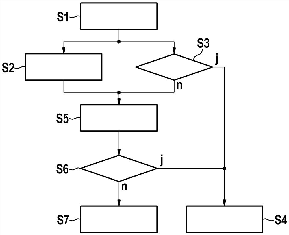

Image

  • Method and device for determining an available fluid volume, braking system
  • Method and device for determining an available fluid volume, braking system

Examples


Embodiment Construction

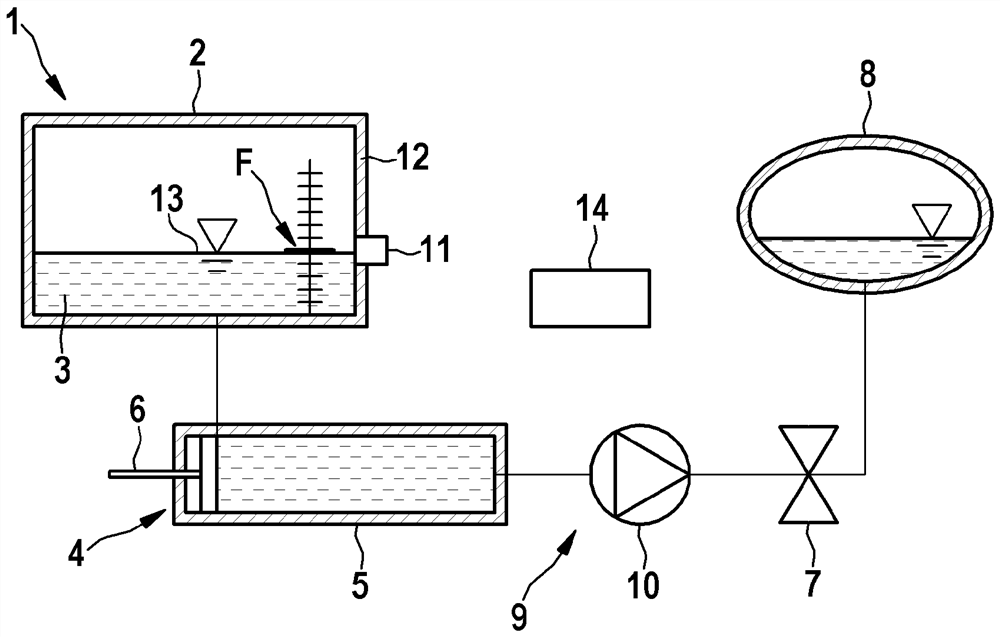
[0017] figure 1 An advantageous braking system 1 of a motor vehicle, which is not shown in detail here, is shown in a simplified illustration. The brake system 1 has a storage tank 2 for receiving and storing a liquid brake medium 3 . The storage tank 2 is fluidically connected to a pressure generator 4 which, according to an exemplary embodiment of the invention, is designed as a hydraulic cylinder 5 with a hydraulic piston 6 displaceably mounted therein. . On the outlet side, the pressure generator 4 is fluidically connected to a controllable valve 7 which selectively releases or blocks the connection of the pressure generator 4 to the brake circuit 8 . The valve 7 is designed, for example, as an electromagnetic switching valve. Optionally, in addition to or as an alternative to the pressure generator 4 there is a further pressure generator 9 which is designed according to an exemplary embodiment of the invention as a rotary pump 10 . If the pressure generator 9 is addit...


PUM


Abstract

The invention relates to a method for determining an available fluid volume in a tank (2) for brake fluid of a brake system (1), wherein the brake system (1) has a pressure generator (4, 9) which is fluidically connected to the tank (2) on the one hand and to at least one brake circuit (8) on the other hand. The pressure generator can be controlled to generate hydraulic pressure in the brake system (1) under the condition that brake fluid is extracted from the tank (2); a predetermined limit value (F) below a filling level for the brake fluid in the tank (2) is monitored by means of a binary sensor (11) assigned to the tank (2). The following operations are regulated: monitoring the actuation of the pressure generator (4, 9); when the current filling level falls below the limit value (F), determining the available liquid volume as a function of the actuation of the pressure generator (4, 9).

Description

technical field [0001] The invention relates to a method and a device for ascertaining the volume of fluid available in a brake fluid reservoir for a brake system having a connection with the reservoir on the one hand and with the reservoir on the other hand. On the one hand, a pressure generator fluidically connected to at least one brake circuit, which can be actuated to generate a hydraulic pressure in the brake circuit when the brake fluid is withdrawn from the storage tank The pressure is monitored by means of a binary sensor assigned to the storage tank below a predetermined limit value for the fill level of the brake fluid in the storage tank. [0002] Furthermore, the invention relates to a brake system with a reservoir for brake fluid; with at least one brake circuit and with the reservoir on the one hand and the at least one brake circuit fluid A technically connected pressure generator configured to: generate hydraulic pressure in at least one brake circuit when br...

Claims


Application Information

Patent Timeline
Patent Type & Authority Applications(China)
IPC IPC(8): B60T17/22
CPCB60T17/225B60T17/22B60T17/221B60T13/662B60T2270/403B60T13/686B60T13/16B60T2270/406G01M3/26G01F23/0007B60T17/08
Inventor F·哈格M·马夸特N·洛夫曼
Owner ROBERT BOSCH GMBH
Learn More