Painting pigment storage box for advertisement design
A storage box and paint technology, applied in the field of painting utensils, can solve the problems of low stirring efficiency of storage boxes, low stirring efficiency of paint storage boxes, etc.
- Summary
- Abstract
- Description
- Claims
- Application Information
AI Technical Summary
Problems solved by technology
Method used
Image
Examples
Embodiment 1
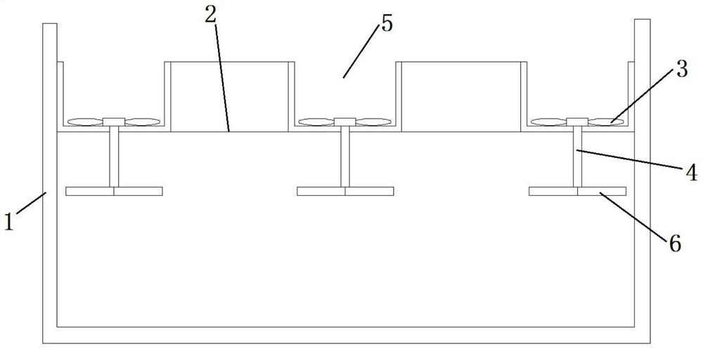
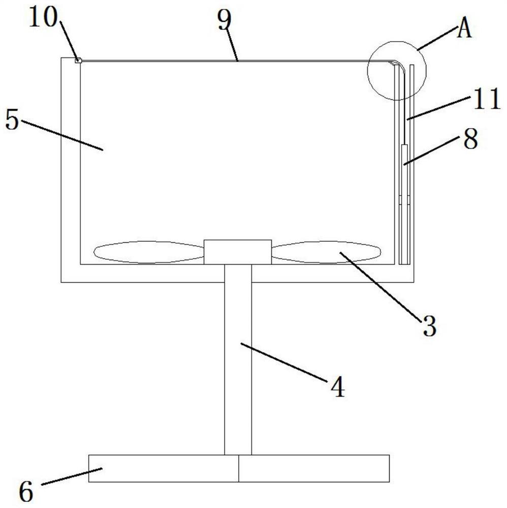
[0040] Such as figure 1 Shown, a kind of paint storage box for advertisement design, comprises box body 1, paint rack 2, stirring paddle 3, stirring shaft 4, driving device and a plurality of paint grooves 5, and described paint rack 2 is fixedly installed in box body 1, a plurality of paint tanks 5 are fixedly installed on the paint rack 2, one end of the stirring shaft 4 is fixedly connected to the stirring paddle 3, and the other end of the stirring shaft 4 is connected to the driving device for transmission. connected, the stirring paddle 3 passes through the bottom side wall of the paint tank 5 and is rotatably connected with the bottom side wall of the paint tank 5, and the driving device is fixedly installed in the inner cavity of the box body 1 and is located in the paint tank 5 under shelf 2.
[0041] Specifically, a plurality of the paint tanks 5 may be arranged side by side, or alternately arranged at intervals. The stirring shaft 4 is connected with the bottom si...
Embodiment 2
[0044] It should be understood that this embodiment at least includes all the technical features of the foregoing embodiments, and further specific descriptions are made on the basis of the foregoing embodiments.
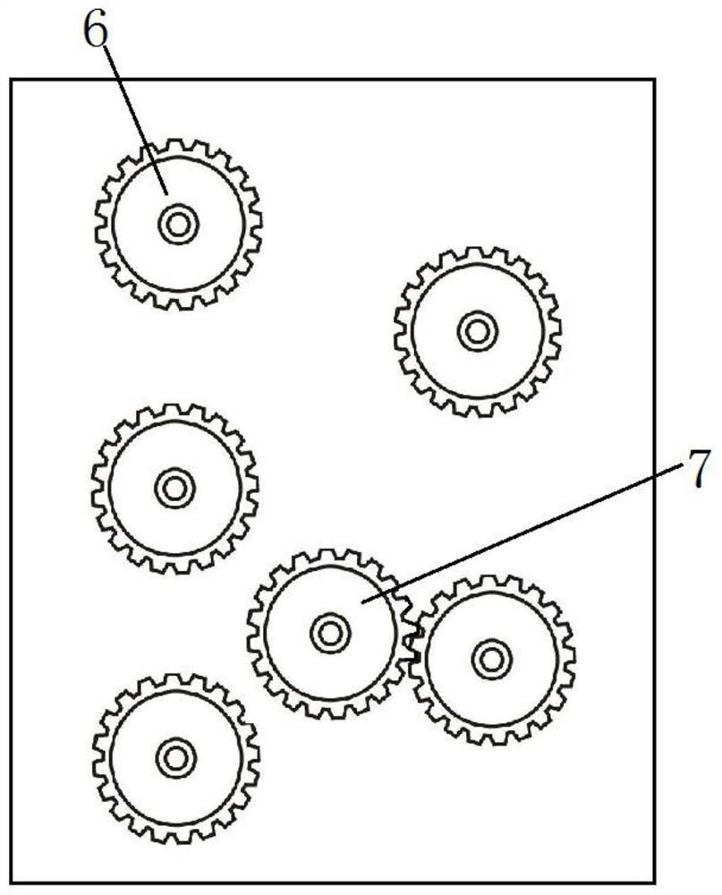
[0045] In this example, if figure 1 as well as figure 2 As shown, the driving device includes a first driving gear 6, a second driving gear 7, a first rotating shaft (not shown in the figure), a moving mechanism (not shown in the figure) and a rotating mechanism (not shown in the figure) , the stirring shaft 4 passes through the axis of the first drive gear 6 and is fixedly connected with the first drive gear 6, and the first rotating shaft passes through the axis of the second drive gear 7 and is fixedly connected with the second drive gear 7 , the first rotating gear meshes with the second driving gear 7, the rotating mechanism is connected with the first rotating shaft and used to drive the first rotating shaft to rotate, the moving mechanism is fixedly install...
Embodiment 3
[0056] In this example, if figure 1 as well as figure 2 As shown, the driving device includes a first driving gear 6, a second driving gear 7, a first rotating shaft, a moving mechanism (not shown in the figure) and a rotating mechanism (not shown in the figure), and the stirring shaft 4 passes through Through the axis of the first driving gear 6 and fixedly connected with the first driving gear 6, the first rotating shaft passes through the axis of the second driving gear 7 and is fixedly connected with the second driving gear 7, the first rotating gear Engaged with the second drive gear 7, the rotating mechanism is connected with the first rotating shaft and used to drive the first rotating shaft to rotate, and the moving mechanism is fixedly installed in the inner cavity of the box body 1 and used to drive the rotating mechanism along the first rotating shaft Move back and forth in the direction of the axis line.
[0057] In this example, if figure 2 As shown, a plural...
PUM
 Abstract
Description
Claims
Application Information
 - Generate Ideas
- Intellectual Property
- Life Sciences
- Materials
- Tech Scout
- Unparalleled Data Quality
- Higher Quality Content
- 60% Fewer Hallucinations
Browse by: Latest US Patents, China's latest patents, Technical Efficacy Thesaurus, Application Domain, Technology Topic, Popular Technical Reports.
© 2025 PatSnap. All rights reserved.Legal|Privacy policy|Modern Slavery Act Transparency Statement|Sitemap|About US| Contact US: help@patsnap.com


