Method for detecting a roughness in an abradable layer in a fan casing

A roughness and wear layer technology, applied in coatings, safety devices, machines/engines, etc., can solve problems such as wear layer degradation, avoid unreasonable returns, save time and money, and speed up inspection.

Pending Publication Date: 2021-12-14
SAFRAN AIRCRAFT ENGINES SAS
View PDF0 Cites 0 Cited by
  • Summary
  • Abstract
  • Description
  • Claims
  • Application Information

AI Technical Summary

Problems solved by technology

Conversely, the wear layer, which may cover the abradable layer, degrades to its full thickness when damaged

Method used


Image

  • Method for detecting a roughness in an abradable layer in a fan casing
  • Method for detecting a roughness in an abradable layer in a fan casing
  • Method for detecting a roughness in an abradable layer in a fan casing

Examples


Embodiment Construction

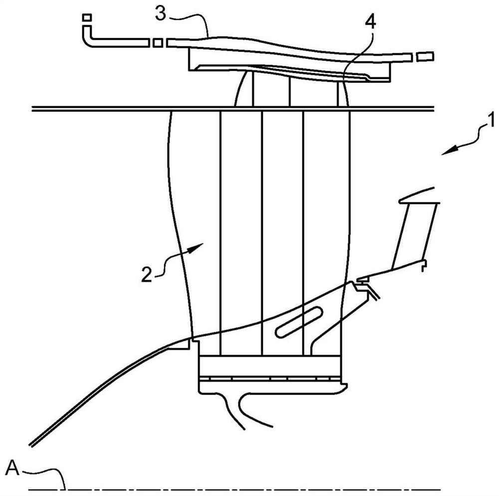
[0055] figure 1 is a partial schematic diagram of a fan of an aircraft turbine.

[0056] In a conventional manner, a turbomachine comprises, from upstream to downstream, i.e. in the direction of flow of the gas flow, a fan, one or more compressors, a combustor, one or more turbines and nozzles for injecting the combustion gases leaving the one or more turbines .

[0057] The fan 1 comprises a blade wheel 2 surrounded by a fan casing 3 which is also called a holding casing since the function of this fan casing is to hold the blades if they break or if debris enters the fan.

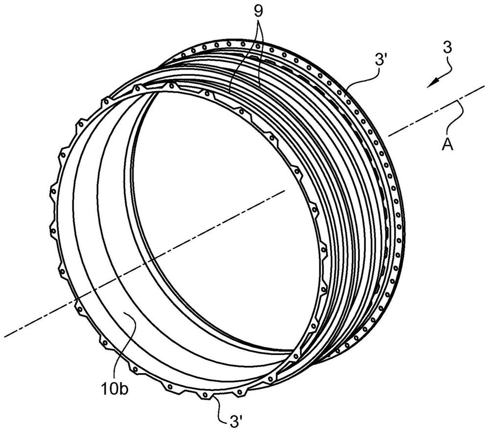
[0058] Such as figure 2 As shown, the fan housing 3 has a substantially cylindrical shape with an axis A of rotation.

[0059] The fan casing comprises at each of its axial ends an annular fixing flange 3'. These flanges 3' are used to fix the casing 3 to the annular wall of the nacelle of the turbine.

[0060] as it should figure 2 As shown, a layer 10b of abradable material is present inside the ...


PUM

PropertyMeasurementUnit
surface roughnessaaaaaaaaaa
thicknessaaaaaaaaaa
thicknessaaaaaaaaaa

Abstract

The invention relates to a method for detecting at least one roughness in a face (10a) of an abradable layer (10) in a fan casing (3). The method comprises a step of applying a first (12) and a second (13) coating covering the first (12), with a respective thickness (N1, N2) and a physical appearance that differ from one another, local appearance of the first coating (12) being indicative of a localized touch-up, and local disappearance of the first coating (12) being indicative of localized replacement of the abradable layer (10).

Description

technical field [0001] The invention relates to a method for detecting at least one roughness on a face of an annular layer of abradable material in a fan housing. The invention also relates to a method for repairing roughness and a fan casing for an aircraft turbine. [0002] Roughness refers to surface inhomogeneities resulting from localized, micron-scale removal of material from the face of the annular layer. Background technique [0003] The prior art is illustrated by documents EP-A1-2 990 660 , EP-A1-3 263 844 , US-A1-2016061049 and EP-A2-2 962 844 . [0004] The main function of fan cases assembled on aircraft turbines is to ensure retention in the event of debris ingestion or loss of fan blades. [0005] Some secondary functions of the fan housing are to ensure the mechanical continuity of forces and moments between the air inlet duct and the intermediate housing shell to enable the attachment of channeled panels such as upstream acoustic shells, support sleeves f...

Claims


Application Information

Patent Timeline
Patent Type & Authority Applications(China)
IPC IPC(8): F01D11/12F01D21/00
CPCF01D11/122F01D21/003F05D2220/36Y02T50/60F01D25/24F05D2230/31F05D2300/516F05D2300/6111
Inventor 克莱门特·布洛劳亚历山大·布兰科塞尔吉·多明格斯文森特·帕斯卡·菲奥里安瓦尔·西拉杰
Owner SAFRAN AIRCRAFT ENGINES SAS
Why Eureka
Try Eureka