Wear-free laminated spiral dewatering equipment with detachable driving device

A driving device, wear-free technology, applied in water/sludge/sewage treatment, chemical instruments and methods, sludge treatment, etc., can solve the problem of inability to install and disassemble, inability to observe normally, and the limit hole is subjected to large force and other problems, to achieve the effect of improving service life, convenient disassembly and installation, and smooth filter channel.

Pending Publication Date: 2021-12-14
吴云萍
View PDF1 Cites 2 Cited by
  • Summary
  • Abstract
  • Description
  • Claims
  • Application Information

AI Technical Summary

Problems solved by technology

[0003] 1. When the driving device is installed below the filter chamber, it is impossible to observe, maintain and repair normally, and it is impossible to quickly install and disassemble, and it is easy to cause the accumulation of leakage mud at the bottom, while the accumulation of leakage mud at the upper end is due to activity The upper end of the ring can only move up and down in a straight line, and it is not easy to get a certain degree of cleaning through the movement of the movable ring itself
[0004] 2. When the driving device is set above the filter cavity, the auxiliary driving rod located at the lower end is pried around the positioning rod at the upper end to swing, because the distance between the main driving rod and the positioning rod is larger than that between the positioning rod and the auxiliary driving rod. The distance between the driving rods is short, so it is easy to overload the driving motor, and even cause excessive force on the limit hole that restricts the positioning rod, resulting in mechanical failures such as wear and deformation.

Method used


Image

  • Wear-free laminated spiral dewatering equipment with detachable driving device
  • Wear-free laminated spiral dewatering equipment with detachable driving device
  • Wear-free laminated spiral dewatering equipment with detachable driving device

Examples


Embodiment Construction

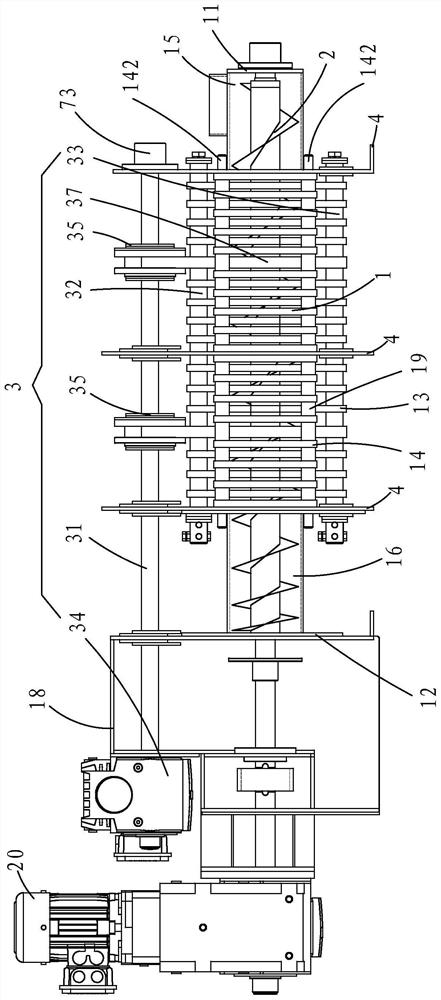
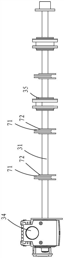
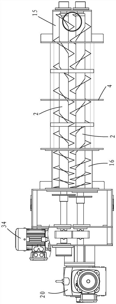
[0060] Such as Figure 1 to Figure 9 As shown, a laminated spiral solid-liquid separator with a detachable driving device includes: a filter cavity 1 , a screw shaft 2 , a driving device 3 , and a plurality of support plates 4 .

[0061] The filter cavity 1, the screw shaft 2 and the driving device 3 are supported and positioned by a plurality of support plates 4; the screw shaft 2 runs through the filter cavity 1; the two ends of the filter cavity 1 are the feed end 11 and the discharge end respectively 12. The feed end 11 of the filter cavity 1 is provided with a mud box 15 , and the discharge end 12 of the filter cavity 1 is provided with a mud box 18 .

[0062] The filter chamber 1 includes two groups of closed ring sheets, the first closed ring sheet group 13 (movable ring) moves under the drive of the drive device 3, and the four holes on the second closed ring sheet group 14 (fixed ring) 141 is fixed to the support plate 4 by the fixing ring pillar 142 and remains sta...


PUM


Abstract

A wear-free laminated spiral solid-liquid separator with a detachable driving device comprises a filtering cavity, a spiral shaft, the driving device and a plurality of supporting plates; the filtering cavity, the spiral shaft and the driving device are supported and positioned through the plurality of supporting plates; the spiral shaft penetrates through the filtering cavity; and the filtering cavity comprises at least two closed ring sheet groups, the main driving rod of the driving device is arranged above the filtering cavity, the upper end of the first closed ring sheet group is driven to do reciprocating circular motion, and the lower end of the first closed ring sheet group is driven to do reciprocating vertical linear motion. The main driving rod, an eccentric device and other driving devices are detachably arranged at the uppermost part of the filtering cavity, so that the driving devices can be prevented from being eroded by filtrate for a long time, the failure rate of the driving devices is reduced, the service life of the driving devices is prolonged, and quick dismounting and mounting during observation and maintenance are facilitated.

Description

technical field [0001] The technical field of the solid-liquid separation equipment of the present invention specifically relates to a wear-free laminated spiral dehydration equipment with a detachable driving device. Background technique [0002] Chinese invention patent 201710239689.7 discloses a multi-axis laminated spiral solid-liquid separator with a pendulum movement. The fixed ring and the movable ring are stacked together to form a cavity structure. Two or more spiral shafts run through it, and the movable ring passes through the external Drive to realize the reciprocating up and down linear motion of the upper end and the reciprocating pendulum motion of the lower end. But, also there is following shortcoming in the technical scheme disclosed by this document: [0003] 1. When the driving device is installed below the filter chamber, it is impossible to observe, maintain and repair normally, and it is impossible to quickly install and disassemble, and it is easy to...

Claims


Application Information

Patent Timeline
Patent Type & Authority Applications(China)
IPC IPC(8): C02F11/125
CPCC02F11/125
Inventor 吴云萍
Owner 吴云萍
Why Eureka
Try Eureka