Impurity filtering device for oil exploitation
A technology of impurity filtration and petroleum, applied in the direction of filtration separation, fixed filter element filter, chemical instrument and method, etc., can solve the problems of high labor cost consumption, low efficiency, etc., to improve filtration efficiency, improve processing efficiency, and avoid clogging Effect
- Summary
- Abstract
- Description
- Claims
- Application Information
AI Technical Summary
Problems solved by technology
Method used
Image
Examples
Embodiment 1
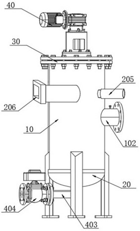
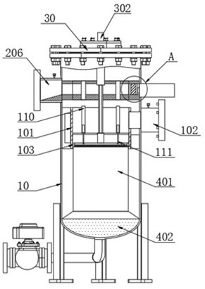
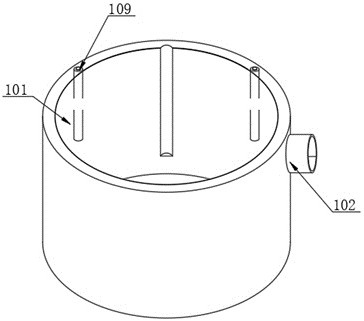
[0036] see Figure 1-6 and Figure 10 As shown, a kind of impurity filtering device used for petroleum development comprises a filter tank 10, the bottom end of the filter tank 10 is screwed with a bottom cover 20, and the top of the filter tank 10 is fixedly connected with a top cover 30 by bolts, and the top cover 30 The top is provided with a stirring motor 40, the inside of the filter tank 10 is provided with a filter mechanism, and the filter mechanism includes a filter frame 101, one side of the filter tank 10 peripheral surface is provided with an oil inlet pipe 102, the inside of the oil inlet pipe 102 is provided with a valve, and One end of the oil pipe 102 communicates with the inside of the filter frame 101, and the two sides of the filter frame 101 are fixedly connected with the inner wall of the filter tank 10 through fixing blocks, and the bottom of the filter frame 101 is provided with a mounting frame 103, and the inside of the mounting frame 103 is provided wit...
Embodiment 2
[0041] see Figure 7-8 As shown, the inside of the filter tank 10 in the present invention is also provided with an impurity removal mechanism. The impurity removal mechanism includes an impurity removal frame 201. Internal fixed connection, the inside of the impurity removal frame 201 is provided with a through hole 202, and the diameter of the through hole 202 is the same as the diameter of the mounting frame 103, the inside of the impurity removal frame 201 is provided with a movable groove 203, and the right side of the movable groove 203 inside A pusher plate 204 is slidingly arranged, and the pusher plate 204 is used to push inside the movable groove 203. The pusher plate 204 pushes the impurities on the upper surface of the filter screen 104 into the inside of the discharge pipe 206, and the impurities are discharged through the discharge pipe 206. collected and processed afterwards;
[0042] Two servo electric cylinders 205 are arranged symmetrically on the right side...
Embodiment 3
[0044] see Figure 9 As shown, the interior of the filter tank 10 in the present invention is also provided with a drive mechanism, the drive mechanism includes a rotating rod 301, and the bottom end of the rotating rod 301 is fixedly connected to the top of the scraper frame 105, and the top end of the rotating rod 301 runs through the movable frame 107 And extend to the top of the movable frame 107, and the inside of the movable frame 107 and the surface of the rotating rod 301 leave a rotation gap, the inner rotation of the top cover 30 is connected with the driving rod 302, the top of the driving rod 302 and the output shaft of the stirring motor 40 One end is fixedly connected by a coupling, and the bottom end of the driving rod 302 is movably provided with a movable rod 303, the driving rod 302 is driven by the output shaft of the stirring motor 40, and the rotating rod 301 is driven by the movable rod 303 to rotate, and then the rotating rod The scraper frame 105 provid...
PUM
 Abstract
Description
Claims
Application Information
 - R&D
- Intellectual Property
- Life Sciences
- Materials
- Tech Scout
- Unparalleled Data Quality
- Higher Quality Content
- 60% Fewer Hallucinations
Browse by: Latest US Patents, China's latest patents, Technical Efficacy Thesaurus, Application Domain, Technology Topic, Popular Technical Reports.
© 2025 PatSnap. All rights reserved.Legal|Privacy policy|Modern Slavery Act Transparency Statement|Sitemap|About US| Contact US: help@patsnap.com


