
Constant on-resistance switching circuit and analog switch

A resistance switch, constant conduction technology, applied in the field of analog circuits, can solve the problems of low linearity of analog switches and the influence of on-resistance on the transmission quality of audio signals, and achieve the effect of improving linearity

Inactive Publication Date: 2021-12-10
广芯电子技术(上海)股份有限公司
View PDF4 Cites 0 Cited by
  • Summary
  • Abstract
  • Description
  • Claims
  • Application Information

AI Technical Summary

Problems solved by technology

[0003] The technical problem to be solved by the present invention is to provide a constant on-resistance switch in order to overcome the defect that the change of the on-resistance of the analog switch in the prior art will affect the transmission quality of the audio signal and cause the linearity of the analog switch to be low. circuits and analog switches

Method used


Image

  • Constant on-resistance switching circuit and analog switch
  • Constant on-resistance switching circuit and analog switch
  • Constant on-resistance switching circuit and analog switch

Examples


Embodiment Construction

[0025] The present invention is further illustrated below by means of examples, but the present invention is not limited to the scope of the examples.

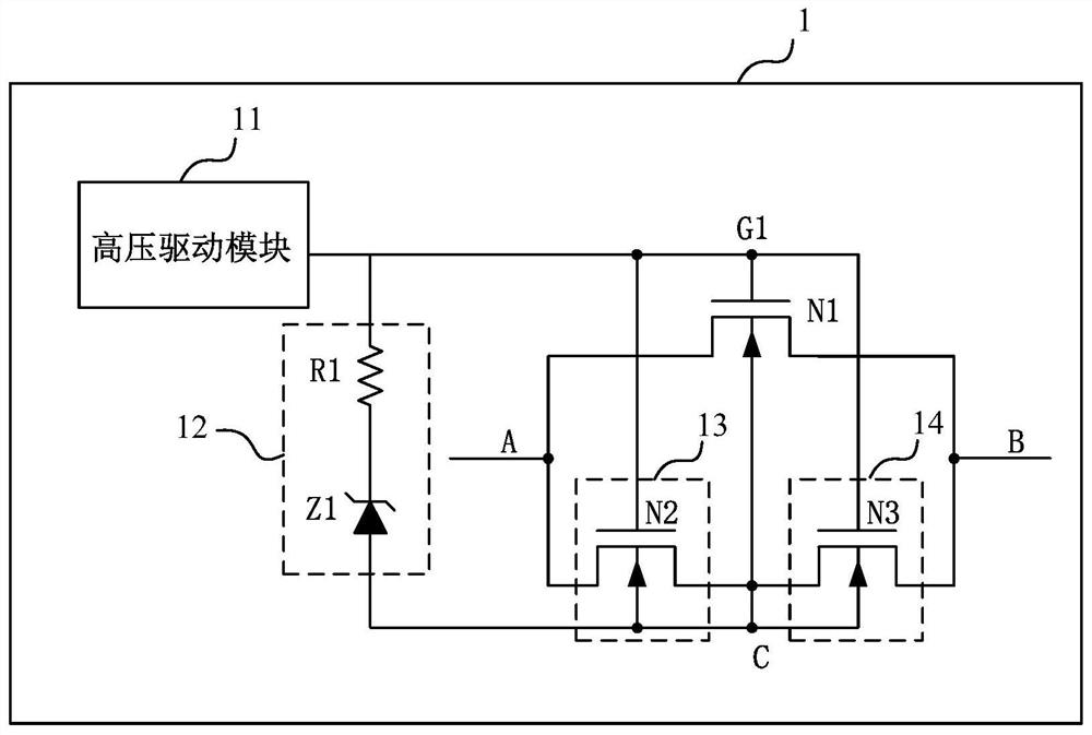
[0026] Such as figure 1 As shown, a constant on-resistance switching circuit 1 provided in this embodiment includes a high-voltage driving module 11, a voltage stabilizing module 12, and a main switching tube N1; wherein:

[0027] The width-to-length ratio of the main switch transistor N1 is greater than a preset threshold;

[0028] The output terminal of the high-voltage driving module 11 is electrically connected to the grid of the main switching tube N1, the input terminal of the voltage stabilizing module 12 is electrically connected to the grid of the main switching tube N1, and the output terminal of the voltage stabilizing module 12 is connected to the lining of the main switching tube N1. Bottom electrical connection;

[0029] A first voltage dividing circuit 13 is provided between the source of the main switching tr...


PUM

PropertyMeasurementUnit
electrical resistanceaaaaaaaaaa

Abstract

The invention discloses a constant on-resistance switching circuit and an analog switch. The circuit comprises a high-voltage driving module, a voltage stabilizing module and a main switching tube, the width-to-length ratio of the main switch tube is greater than a preset threshold value; the output end of the high-voltage driving module is electrically connected with the grid electrode of the main switch tube, the input end of the voltage stabilizing module is electrically connected with the grid electrode of the main switch tube, and the output end of the voltage stabilizing module is electrically connected with the substrate of the main switch tube; a first voltage division circuit is arranged between the source electrode of the main switch tube and the substrate, and a second voltage division circuit is arranged between the drain electrode of the main switch tube and the substrate, so that the substrate voltage of the main switch tube is half of the sum of the source electrode voltage and the drain electrode voltage of the main switch tube. A high-level signal is input into the grid electrode of the main switch tube through the high-voltage driving module, the main switch tube is switched on, and the voltage difference between the grid electrode of the main switch tube and the substrate meets the preset voltage threshold value based on the voltage stabilizing module, the first voltage dividing circuit and the second voltage dividing circuit, so that the main switch tube reaches the constant on-resistance, and the linearity of the analog switch is improved.

Description

technical field [0001] The invention relates to the technical field of analog circuits, in particular to a constant on-resistance switch circuit and an analog switch. Background technique [0002] Analog switches are widely used. For analog switches used to transmit audio signals, it is necessary to ensure constant on-resistance in various signal ranges, and the change in on-resistance of analog switches will affect the transmission quality of audio signals. For example, in audio In the process of signal transmission, when the on-resistance of the analog switch changes, data transmission errors and audio quality deterioration usually occur, resulting in low linearity of the analog switch. Contents of the invention [0003] The technical problem to be solved by the present invention is to provide a constant on-resistance switch in order to overcome the defect that the change of the on-resistance of the analog switch in the prior art will affect the transmission quality of t...

Claims


Application Information

Patent Timeline
Patent Type & Authority Applications(China)
IPC IPC(8): H03K17/687
CPCH03K17/6871
Inventor 虞志雄戴忠伟张阳
Owner 广芯电子技术(上海)股份有限公司
Learn More