Pitching driving device for vehicle-mounted communication antenna
A driving device and vehicle communication technology, applied to antennas, antennas suitable for movable objects, electrical components, etc., can solve the problems of low degree of automation, inconvenient antennas, and inability to meet the needs of use, so as to improve stability and safety effect
- Summary
- Abstract
- Description
- Claims
- Application Information
AI Technical Summary
Problems solved by technology
Method used
Image
Examples
Embodiment 1
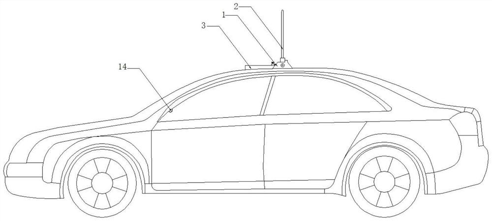
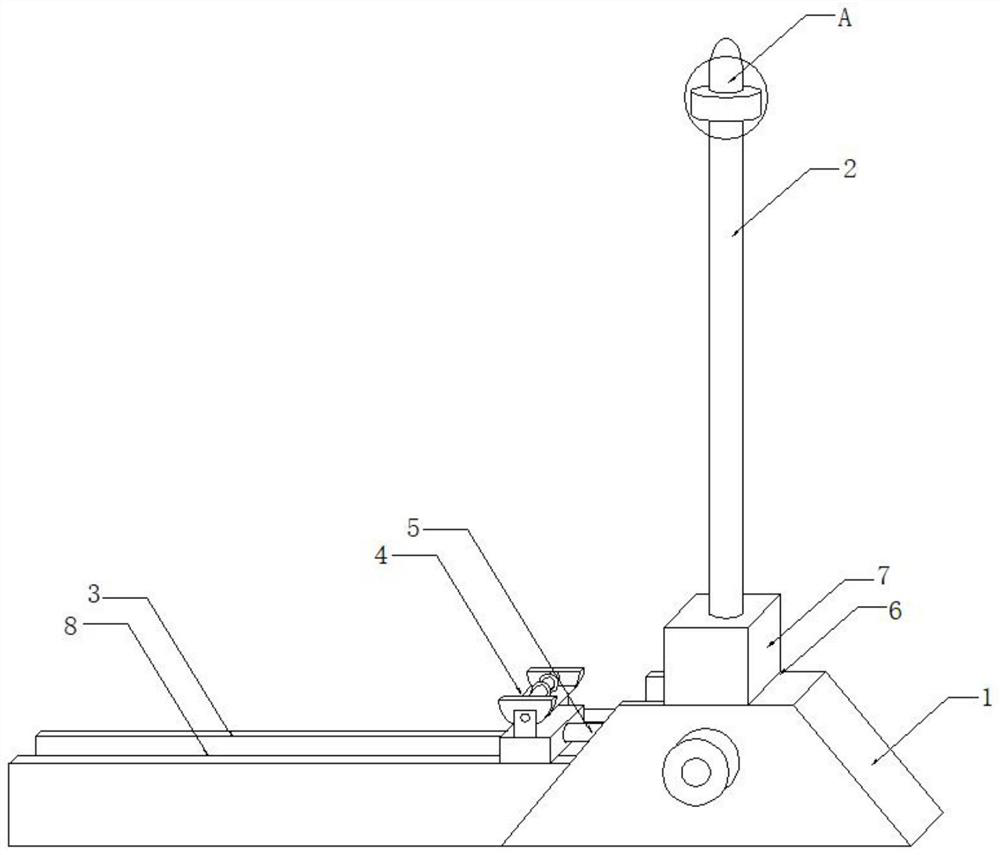
[0028] Example 1: See Figure 1-10 , the present invention provides a technical solution: a pitch drive device for vehicle-mounted communication antennas, including an automatic pitch drive device, the automatic pitch drive device includes a movable mount 1, an antenna body 2, a guide plate 3, and a slide adjuster 4 And the contact type longitudinal push mechanism 5, the movable mounting seat 1 is fixed on the top of the vehicle and has an installation opening 6 inside, and a rotator 7 is installed in the installation opening 6, the upper end of the rotator 7 is connected with the antenna body 2, and the guide plate 3. It is installed horizontally on the left side of the movable mounting base 1 and has a guide groove 8 on the surface. The slide regulator 4 is set in the guide groove 8 and is provided with a rolling bracket 9 and a driving mechanism 10 sequentially from top to bottom. The driving mechanism 10 is installed below the rolling bracket 9 and is movably installed in ...
Embodiment 2
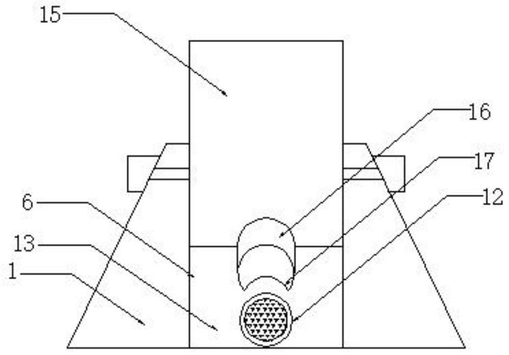
[0030] Example 2, such as image 3 , the technical solution of this embodiment is the rotator 7 installed on the above-mentioned automated pitching drive device, the rotator 7 includes a flap 15 inserted in the installation opening 6 and a butt joint 16 fixed to the lower end of the flap 15, the flap 15 The two sides of the butt joint 16 are rotatably connected with the inner wall of the installation port 6. The butt joint 16 is arranged in an inclined shape and the lower end is provided with a notch 17. The butt joint 16 is used with the jack 11. This design method is convenient for the end of the electric push rod 33 to pass through Insert it into the notch 17 and push the turning plate 15 to rotate, so as to achieve the secondary adjustment of the antenna body 2 .
Embodiment 3
[0031] Example 3, such as Figure 6, the technical solution of the present embodiment is the rolling bracket 9 installed on the above-mentioned automatic pitching drive device, the rolling bracket 9 is composed of a supporting plate 18, a side plate 19, a transverse shaft 20, a splint 21, a buffer spacer 22, a pressure The sensor 23 and the micro motor 24 are composed, the side plates 19 are divided into two groups and installed symmetrically at the two ends of the supporting plate 18, the two ends of the transverse shaft 20 are rotatably installed between the two groups of side plates 19, and the splint 21 is symmetrically arranged in two groups and The lower end is rotatably connected with the horizontal shaft 20, the buffer spacer 22 is located between two groups of splints 21 and has a corrugated structure, the pressure sensor 23 is located directly below the buffer spacer 22 and is connected to a controller 25 through a line, and the controller 25 is connected to the two ...
PUM
 Abstract
Description
Claims
Application Information
 - Generate Ideas
- Intellectual Property
- Life Sciences
- Materials
- Tech Scout
- Unparalleled Data Quality
- Higher Quality Content
- 60% Fewer Hallucinations
Browse by: Latest US Patents, China's latest patents, Technical Efficacy Thesaurus, Application Domain, Technology Topic, Popular Technical Reports.
© 2025 PatSnap. All rights reserved.Legal|Privacy policy|Modern Slavery Act Transparency Statement|Sitemap|About US| Contact US: help@patsnap.com


