
Energy-saving oil-immersed transformer equipment

An oil-immersed transformer, energy-saving technology, applied in transformer/inductor cooling, transformer/inductor components, transformer/inductor coil/winding/connection, etc. Liquid heat dissipation effect and other issues, to improve the heat dissipation effect, improve the heat transfer effect, and achieve the effect of continuous heat dissipation

Pending Publication Date: 2021-12-10
HEFEI JINGXI ELECTRICAL EQUIP
View PDF0 Cites 3 Cited by
  • Summary
  • Abstract
  • Description
  • Claims
  • Application Information

AI Technical Summary

Problems solved by technology

[0003] At present, when the oil-immersed transformer is working, its winding is immersed in the oil, and the oil is used to exchange heat with the winding to realize the cooling of the winding. In the oil tank, usually a number of heat dissipation fins are fixed outside the oil tank, and the heat in the oil is conducted outward by using the heat dissipation fins to ensure that the temperature of the oil is not too high. This heat dissipation method is more traditional, and the heat dissipation effect of the oil is good. Bad depends too much on whether there is air circulation in the external environment. When there is no air circulation in the external environment or the air circulation effect is not good, the heat dissipation effect of the oil will also be affected, which will reduce the cooling effect of the winding

Method used


Image

  • Energy-saving oil-immersed transformer equipment
  • Energy-saving oil-immersed transformer equipment
  • Energy-saving oil-immersed transformer equipment

Examples


Embodiment Construction

[0029] The technical solution of this patent will be further described in detail below in conjunction with specific embodiments.

[0030] Embodiments of the present patent are described in detail below, examples of which are shown in the drawings, wherein the same or similar reference numerals designate the same or similar elements or elements having the same or similar functions throughout. The embodiments described below by referring to the figures are exemplary and are only used for explaining the patent, and should not be construed as limiting the patent.

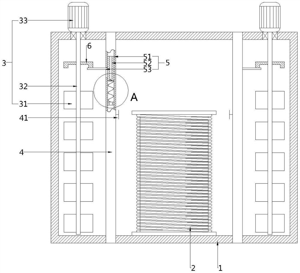
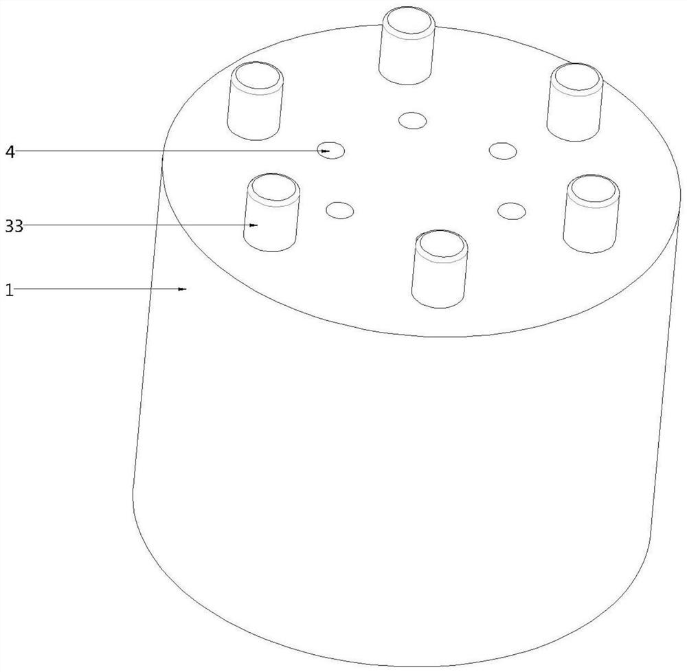
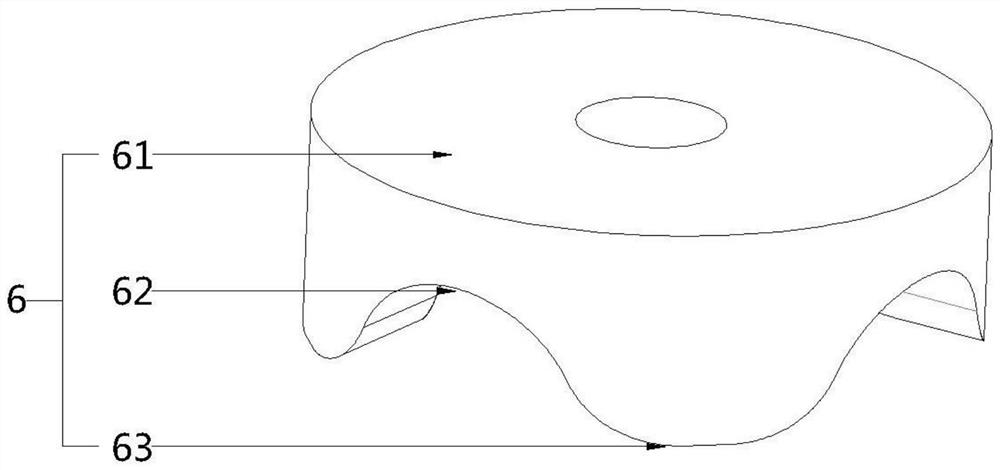
[0031] see figure 1 , this embodiment provides an energy-saving oil-immersed transformer device, including an oil tank 1, a winding 2, a stirring part 3, an air duct 4, an air supply part 5 and a driving part 6, and the winding 2 is arranged on the oil tank 1 inside and submerged in the oil, the air pipe 4 is arranged on one side of the winding 2, both ends of the air pipe 4 communicate with the outside through the sid...


PUM


Abstract

The invention provides energy-saving oil-immersed transformer equipment, and belongs to the technical field of oil-immersed transformers, the energy-saving oil-immersed transformer equipment comprises an oil tank, a winding, a stirring part, an air pipe, an air supply part and a driving part, the winding is arranged in the oil tank and immersed in oil, and the air pipe is arranged on one side of the winding; the two ends of the air pipe penetrate through the side wall of the oil tank to be communicated with the outside, the air supply part is movably arranged in the air pipe, the stirring part is arranged at the edge position in the oil tank and used for stirring oil in the oil tank, and when the stirring part stirs the oil, the driving part can drive the air supply part to reciprocate in the length direction in the corresponding air pipe. Compared with the prior art, full contact between oil and the winding can be achieved, the heat dissipation effect of the winding is improved, continuous heat dissipation of the winding can be achieved through continuous circulation of air in the air pipe, and the windingequipment has the advantage of being good in heat dissipation effect.

Description

technical field [0001] The invention belongs to the technical field of oil-immersed transformers, in particular to energy-saving oil-immersed transformer equipment. Background technique [0002] As a general-purpose transformer, the oil-immersed transformer plays an important role in the power supply and distribution systems of industrial and mining enterprises and civil buildings. [0003] At present, when the oil-immersed transformer is working, its winding is immersed in the oil, and the oil is used to exchange heat with the winding to realize the cooling of the winding. Generally, a number of cooling fins are fixed on the outside of the fuel tank, and the heat in the oil is conducted outward by using the cooling fins to ensure that the temperature of the oil is not too high. This cooling method is more traditional, and the cooling effect of the oil is good. Bad depends too much on whether there is air circulation in the external environment. When there is no air circula...

Claims


Application Information

Patent Timeline
Patent Type & Authority Applications(China)
IPC IPC(8): H01F27/28H01F27/12H01F27/08
CPCH01F27/2876H01F27/12H01F27/085
Inventor 姜景泰
Owner HEFEI JINGXI ELECTRICAL EQUIP
Learn More