Creasing machine and creasing and cementing machine

An indentation machine and indentation glue technology, which is applied in the directions of transportation and packaging, machining/deformation, object supply, etc., can solve the problems of defective products with reduced glue binding accuracy, relative position movement, and indentation position offset.

Pending Publication Date: 2021-12-10
NINGBO RONGHUA OFFICE EQUIP
View PDF11 Cites 0 Cited by
  • Summary
  • Abstract
  • Description
  • Claims
  • Application Information

AI Technical Summary

Problems solved by technology

The creasing machine in the prior art includes multiple structures for conveying paper, and these structures are driven by their own motors. This control method needs to coordinate the start-up time of each motor, and due to the difference between the motors, resulting in The transmission error is large, and it is easy to cause the indentation position to shift, and the indentation position shift will also lead to a decrease in the accuracy of the subsequent glue binding.
In addition, when the paper is sent to the binding position on the binding machine, the position of the paper is easily changed due to the vibration or collision of the creasing machine or the binding machine before the lifting structure and the related binding structure on the binding machine are in place. Resulting in a decrease in the accuracy of glue binding and resulting in defective products
In addition, the relative position of the existing creasing machine and glue binding machine will move due to vibration and other reasons during operation, resulting in a decrease in the accuracy of the subsequent glue binding

Method used


Image

  • Creasing machine and creasing and cementing machine
  • Creasing machine and creasing and cementing machine
  • Creasing machine and creasing and cementing machine

Examples


Embodiment 1

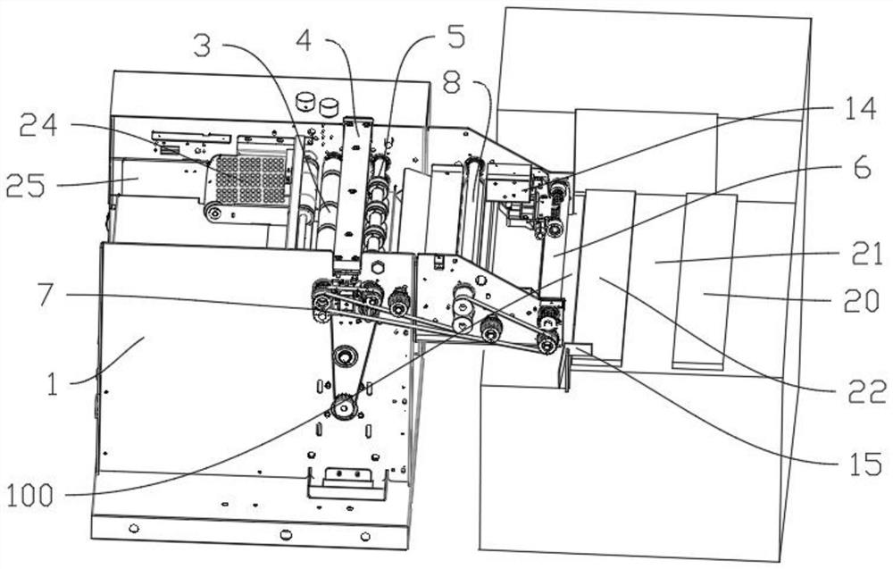
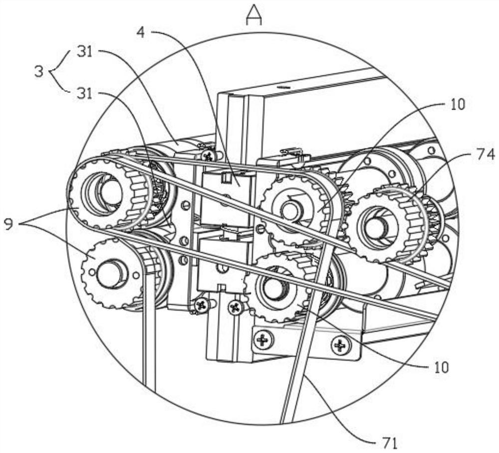
[0039] Such as Figures 1 to 11 As shown, a creasing machine is provided in this embodiment, which includes a creasing frame 1, and also includes a transmission mechanism 7 and a control module. The creasing frame 1 is sequentially provided with a paper backing plate 25, The suction paper assembly 24, the first rubber roller assembly 3, the creasing assembly 4, the second rubber roller assembly 5, the third rubber roller assembly 8 and the paper feeding roller 6, the paper feeding roller 6 is arranged on the paper output of the creasing frame 1 end 100, the creasing frame 1 is also provided with a motor 2, the first rubber roller assembly 3 is provided with a first transmission member, the second rubber roller assembly 5 is provided with a second transmission member, and the third rubber roller assembly 8 is provided with a A third transmission part is provided, and a fourth transmission part is provided on the paper feed roller 6. The motor 2 drives the transmission mechanism...

Embodiment 2

[0047] Such as Figure 12 , 13 As shown, in this embodiment, a creasing and perfecting machine is provided, including the creasing machine in Embodiment 1, and also includes a glue-binding frame 27, and a magnet block 29 is passed between the creasing frame 1 and the glue-binding frame 27 Connection; the indentation frame 1 is provided with a screw 30, the screw 30 is a positive and negative thread screw, that is, the thread at one end of the screw 30 is left-handed, and the thread at the other end is right-handed. The protrusion 31 of the distance between the magnet blocks 29, the shape of the protrusion 31 can preferably be a nut type; one end of the screw rod 30 is threadedly connected to the indentation frame 1 and can be inserted into the indentation frame 1, and the other end is threadedly connected with a U-shaped The casing 28 and the magnet block 29 are connected in the casing 28 by bolts, and the screw rod 30 is connected to the magnet block 29 by connecting the cas...


PUM


Abstract

The invention relates to a creasing machine. The creasing machine comprises a creasing rack and a transmission mechanism, wherein a first rubber roller assembly, a creasing assembly and a paper feeding roller are sequentially arranged on the creasing rack in the paper conveying direction; a motor is further arranged on the creasing rack; a first transmission part is arranged on the first rubber roller assembly; a fourth transmission part is arranged on the paper feeding roller; the motor drives the transmission mechanism and is matched with the first transmission part and the fourth transmission part through the transmission mechanism to drive the first rubber roller assembly and the paper feeding roller to rotate simultaneously; a paper pressing mechanism is arranged at the paper outlet end, and when the paper stops on the paper feeding roller, the paper pressing mechanism presses the paper to prevent the paper from moving. The invention further provides a creasing and cementing machine. The creasing and cementing machine comprises the creasing machine and further comprises a cementing rack, wherein the creasing rack and the cementing rack are connected through a magnet block. The technical problems that in the prior art, a plurality of motors are used for controlling paper conveying in all modules during creasing of a creasing machine, so that conveying errors are large, the defective product rate is high, and the cementing precision is low due to vibration of the creasing machine or a cementing machine are solved.

Description

technical field [0001] The invention relates to the technical field of indentation machines, in particular to an indentation machine and an indentation adhesive machine. Background technique [0002] The creasing machine is a device that can produce creasing on the paper, which is convenient for the subsequent processing of the paper, including the operation of glue binding after the creasing of the paper, specifically, after the creasing of the paper on the creasing machine, From the output end of the creasing machine, it is sent to the perfect binding machine for perfect binding. The creasing machine in the prior art includes multiple structures for conveying paper, and these structures are driven by their own motors. This control method needs to coordinate the start-up time of each motor, and due to the difference between the motors, resulting in Larger transmission errors can also easily cause indentation position shifts, which will also lead to a decrease in the accura...

Claims


Application Information

Patent Timeline
Patent Type & Authority Applications(China)
IPC IPC(8): B31F1/10B31F5/04B07C5/10B65H5/22
CPCB31F1/10B31F5/04B07C5/10B65H5/224
Inventor 杜建国
Owner NINGBO RONGHUA OFFICE EQUIP
Why Eureka
Try Eureka