
Damping mechanism and mixer truck

A shock-absorbing mechanism and shock-absorbing technology, applied in springs/shock absorbers, cement mixing devices, mechanical equipment, etc., can solve the problem that the reducer cannot achieve any angle, so as to ensure stability and safety, and improve service life. , Improve the effect of shock absorption

Pending Publication Date: 2021-12-10
SUOTE TRANSMISSION EQUIP
View PDF0 Cites 1 Cited by
  • Summary
  • Abstract
  • Description
  • Claims
  • Application Information

AI Technical Summary

Problems solved by technology

[0005] Therefore, the technical problem to be solved by the present invention is to overcome the defect that the speed reducer of the mixer truck in the prior art cannot realize the deflection at any angle on the damping mechanism.

Method used


Image

  • Damping mechanism and mixer truck
  • Damping mechanism and mixer truck
  • Damping mechanism and mixer truck

Examples


Embodiment 1

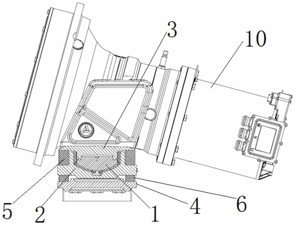
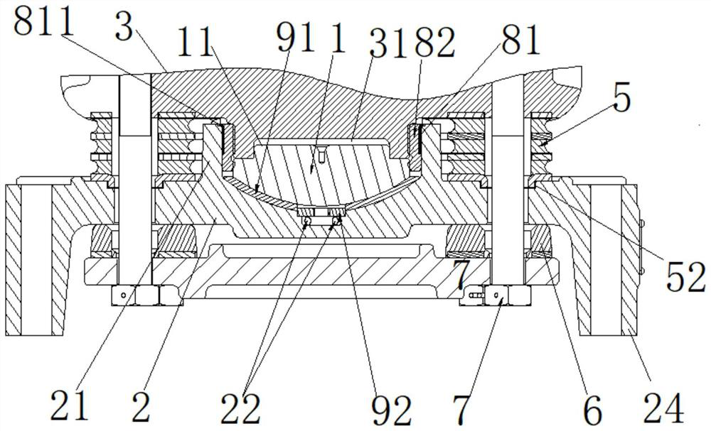
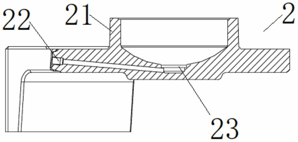
[0060] This embodiment provides a shock absorbing mechanism, such as figure 1 and figure 2 As shown, it includes a deflection part 1 , a support seat 2 , a fixed seat 3 , a bottom plate 4 , a first shock absorber 5 , a second shock absorber 6 and a fastener 7 . Wherein, the bottom surface of the swing part 1 is an arc surface; the support seat 2 has a mounting groove matching the shape of the bottom surface of the swing part 1, and the swing part 1 is rotatably arranged in the mounting groove; The outer circumference of the top of the installation groove is protrudingly provided with an annular sleeve part 21; the fixed seat 3 is arranged on the top of the support seat 2 and is fixedly connected with the swing part 1; the bottom plate 4 is arranged at the bottom of the support seat 2; The shock element 5 is arranged between the fixed seat 3 and the support seat 2; the second shock absorber 6 is arranged between the support seat 2 and the bottom plate 4; the fasteners 7 are t...

Embodiment 2

[0076] This embodiment provides a mixer truck, which includes the shock absorbing mechanism and the speed reducer 10 in Embodiment 1, the speed reducer 10 is arranged on the shock absorbing mechanism, and the outer edge of the support seat 2 is provided with a downwardly bent installation portion 24, The mounting part 24 is provided with a plurality of threaded holes, and bolts pass through the threaded holes on the mounting part 24 and the vehicle frame to fix the support base 2 on the vehicle frame.

[0077] In the mixer truck with this structure, the fixed seat 3 on it is fixedly connected with the swing part 1, and the speed reducer 10 is arranged on the swing part 1. The pendulum part 1 swings at any angle in the installation groove of the support seat 2 to absorb the vibration and impact force of the mixing tank. The shock-absorbing mechanism has good impact resistance and improves the stability and safety of the mixer truck.


PUM


Abstract

The invention provides a damping mechanism and a mixer truck. The damping mechanism comprises a deflection part, a supporting seat, a fixing seat, a bottom plate, a first damping piece, a second damping piece and a fastening piece. When the damping mechanism with the structure is used, the fixing seat can be directly used as a shell of a speed reducer; or the fixing seat serves as a component of the damping mechanism and is connected with the shell of the speed reducer; and the supporting seat is connected with a mixer truck frame, the gravity and vibration impact force of a mixing barrel are transmitted to the first damping piece through the fixing seat, the first damping piece absorbs horizontal and axial force caused by the gravity of the mixing barrel and the vibration impact force, and stable operation of the mixer truck is guaranteed. The fixing seat is fixedly connected with the deflection part, the speed reducer is arranged on the deflection part, when the stirring barrel vibrates, vibration impact force is transmitted to the speed reducer and the deflection part, the deflection part deflects at any angle in a mounting groove of the supporting seat so as to absorb the vibration impact force of the stirring barrel, the damping mechanism is good in shock resistance, and the stability and safety of operation of the mixer truck are further improved.

Description

technical field [0001] The invention relates to the technical field of shock absorption of a mixing tank, in particular to a shock absorption mechanism and a mixer truck. Background technique [0002] Concrete mixer truck is a kind of mechanical equipment commonly used in construction. The main bearing of the reducer on it and the two support wheels at the rear support the weight of the entire mixing tank and concrete. Due to the heavy weight of the mixing tank and concrete, during the mixing process It will drive the vibration of the entire mixing tank; in addition, the bumps caused by the potholes in the road or the inertial impact caused by the driver's brake will act on the main bearing. Most of the load of the mixing tank needs to be borne by the main bearing of the reducer. The main bearing needs to bear both radial load and axial load. The main bearing of the reducer needs to have a certain self-aligning function. For this reason, the mixing tank is equipped with a s...

Claims


Application Information

Patent Timeline
IPC IPC(8): B28C5/42F16F15/08
CPCB28C5/42B28C5/4203F16F15/08F16F15/085
Inventor 朱仕元倪超张磊
Owner SUOTE TRANSMISSION EQUIP
Learn More