Electrostatic dust collector with high cleaning efficiency for coal cleaning
An electrostatic precipitator, a high-efficiency technology, applied in the direction of electrostatic separation, electrode cleaning, etc., can solve the problems of unable to remove the smoke and dust from the anode plate, and the smoke and dust are easy to float into the flue gas again, so as to prevent it from floating out again and ensure the adsorption efficiency.
- Summary
- Abstract
- Description
- Claims
- Application Information
AI Technical Summary
Problems solved by technology
Method used
Image
Examples
Embodiment 1
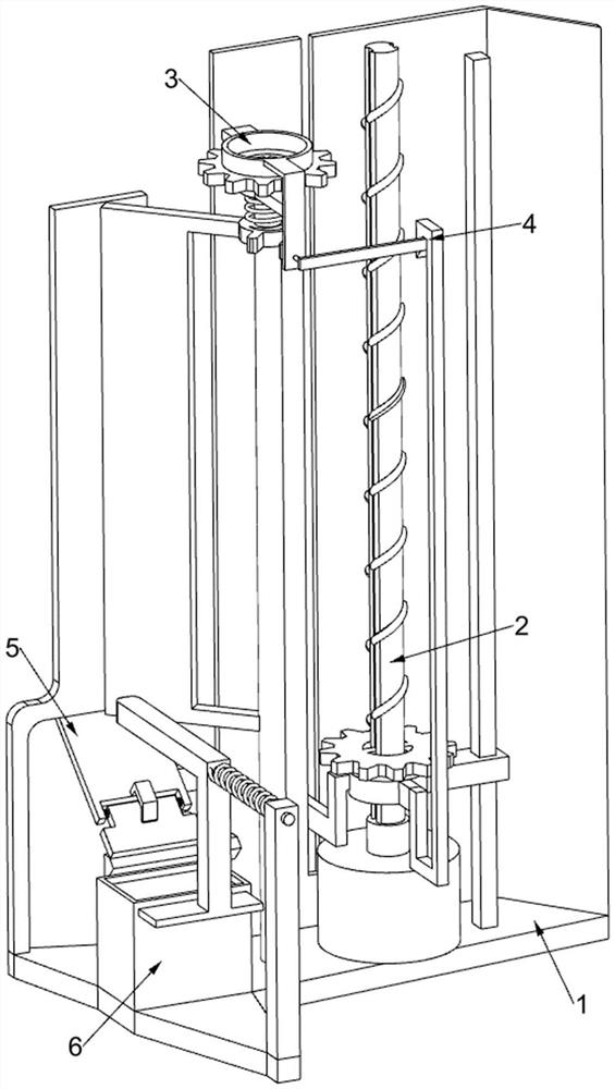
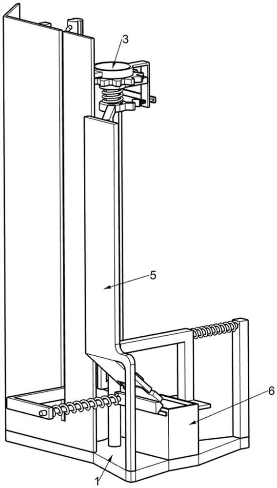
[0025] An electrostatic precipitator with high cleaning efficiency for coal cleaning, such as Figure 1-8 As shown, it includes a first fixed frame 1 , a lifting mechanism 2 and a rotating mechanism 3 , the lifting mechanism 2 is arranged on the first fixed frame 1 , and the rotating mechanism 3 is arranged on the first fixed frame 1 .
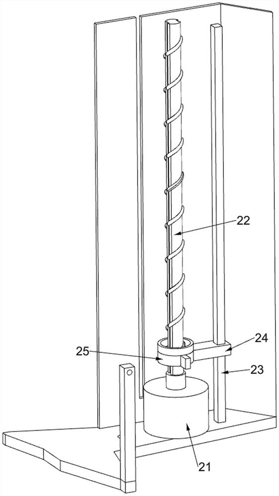
[0026] Lifting mechanism 2 includes motor 21, screw rod 22, fixed rod 23, slide block 24 and nut 25, and motor 21 is installed on the first fixed frame 1, and motor 21 can drive screw rod 22 and its upper device to rotate through output shaft, screw rod 22 Connected to one end of the output shaft of the motor 21, the fixed rod 23 is connected to the top of the first fixed frame 1, the slider 24 is slidably connected to the fixed rod 23, the nut 25 is threaded on the screw rod 22, and the screw rod 22, the nut 25 and the fixed With the cooperation of the rod 23, the nut 25 and its upper device will reciprocate up and down, and the nut 25 is con...
Embodiment 2
[0030] On the basis of Example 1, such as Figure 7As shown, a locking mechanism 4 is also included. The locking mechanism 4 is arranged on the second fixed frame 32. The locking mechanism 4 is used to temporarily limit the anode plate 39. The locking mechanism 4 includes a wedge-shaped frame 41, a first Slide bar 42, fixed plate 43, the second wedge block 44 and the second back-moving spring 45, wedge frame 41 is connected on the nut 25, and wedge frame 41 is used for promoting the reset of fixed plate 43, and the second fixed frame 32 is slidingly connected with The first slide bar 42, one end of the first slide bar 42 is connected with the fixed plate 43, the fixed plate 43 is in contact with the wedge frame 41, the second wedge block 44 is connected with the other end of the first slide bar 42, the second fixed frame 32 and the second A second return spring 45 is connected between the wedge blocks 44 , and through cooperation between the second wedge block 44 and the secon...
Embodiment 3
[0033] On the basis of Example 2, such as Figure 8 As shown, it also includes a scraping mechanism 5, the scraping mechanism 5 is arranged on the first fixed frame 1, and the scraping mechanism 5 is used to scrape off the smoke and dust on the anode plate 39, and the scraping mechanism 5 includes a fourth fixed frame 51. Rotating plate 52, stop frame 53, second torsion spring 54, fifth fixed frame 55, second slide bar 56, scraper 57 and third return spring 58, fourth fixed frame 51 is connected to the top of first fixed frame 1 , the fourth fixed frame 51 is in contact with the anode plate 39, the rotating plate 52 is rotatably connected to the fourth fixed frame 51, the stop frame 53 is connected to the fourth fixed frame 51, and under the action of the block frame 53, the rotating plate 52 will The extruding scraper 57 and its upper device move, and the stop frame 53 is in contact with the rotating plate 52. A second torsion spring 54 is symmetrically connected between the ...
PUM
 Abstract
Description
Claims
Application Information
 - R&D
- Intellectual Property
- Life Sciences
- Materials
- Tech Scout
- Unparalleled Data Quality
- Higher Quality Content
- 60% Fewer Hallucinations
Browse by: Latest US Patents, China's latest patents, Technical Efficacy Thesaurus, Application Domain, Technology Topic, Popular Technical Reports.
© 2025 PatSnap. All rights reserved.Legal|Privacy policy|Modern Slavery Act Transparency Statement|Sitemap|About US| Contact US: help@patsnap.com


