
Thyristor driving circuit

A technology of thyristor drive and thyristor, which is applied in the field of circuit electronics, can solve the problems of large loss and low efficiency of the drive circuit, and achieve the effects of reducing the area, improving reliability, and reducing the loss of the drive circuit

Pending Publication Date: 2021-12-07
SHENZHEN YINGFEIYUAN TECH CO LTD
View PDF0 Cites 2 Cited by
  • Summary
  • Abstract
  • Description
  • Claims
  • Application Information

AI Technical Summary

Problems solved by technology

[0003] In order to reduce the gate loss of the thyristor, the drive circuit is usually driven in the form of pulses. The existing thyristor drive circuit often uses resistors or other passive devices to limit the current of the gate drive current of the thyristor, which leads to large loss of the drive circuit and low efficiency. Low

Method used


Image

  • Thyristor driving circuit
  • Thyristor driving circuit
  • Thyristor driving circuit

Examples


Embodiment

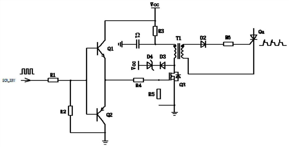
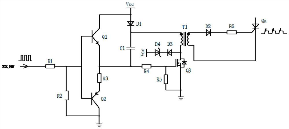
[0030] The present invention provides a thyristor drive circuit, comprising a power supply Vcc, a drive signal input terminal, an auxiliary switch circuit, a main switch circuit, a remagnetic circuit, an energy storage capacitor C1, a diode D1 and a thyristor Qa; the drive signal input terminal is connected to the auxiliary switch circuit , the drive signal input terminal is used to input the drive signal SCR_DRV to control the opening / closing of the auxiliary switch circuit. One terminal node of the energy storage capacitor C1 is divided into two routes, the first route is connected to the power supply Vcc through the diode D1, and the second route is connected to the transformer One end of the primary side of T1 and the other end node of the energy storage capacitor C1 are divided into two paths, the first path is connected to the auxiliary switch circuit, the second path is connected to the other end of the primary side of the transformer T1 through the main switch circuit, a...


PUM


Abstract

The invention provides a thyristor driving circuit which comprises a power supply Vcc, a driving signal input end, an auxiliary switch circuit, a main switch circuit, a complex magnetic circuit, an energy storage capacitor C1, a diode D1, a transformer T1 and a thyristor Qa. The driving signal input end is connected to the auxiliary switch circuit and used for inputting a driving signal to control on / off of the auxiliary switch circuit, a node at one end of the energy storage capacitor C1 is divided into two paths, the first path is connected to a power supply Vcc through a diode D1, the second path is connected to one end of a primary side of the transformer T1, a node at the other end of the energy storage capacitor C1 is divided into two paths, the first path is connected to the auxiliary switch circuit, the second path is connected to the other end of the primary side of the transformer T1 through the main switch circuit, the complex magnetic circuit is connected to one end of the primary side of the transformer T1, and the thyristor Qa is connected to the secondary side of the transformer T1. According to the driving circuit, the loss of the driving circuit, the requirement for power supply power and the driving cost are effectively reduced, the area of a driving board is reduced, and the reliability of the driving circuit is improved.

Description

technical field [0001] The invention belongs to the technical field of circuit electronics, in particular to a thyristor driving circuit. Background technique [0002] Thyristor is the abbreviation of thyristor, also known as silicon controlled rectifier. Compared with other power electronic devices, thyristors can withstand the highest voltage and current capacity, and work reliably, so they are widely used in many high-power and strong interference scenarios. [0003] In order to reduce the gate loss of the thyristor, the drive circuit is usually driven in the form of pulses. The existing thyristor drive circuit often uses resistors or other passive devices to limit the current of the gate drive current of the thyristor, which leads to large loss of the drive circuit and low efficiency. Low. [0004] Therefore, related technologies still need to be improved. Contents of the invention [0005] The technical problem to be solved by the present invention is to provide a ...

Claims


Application Information

Patent Timeline
Patent Type & Authority Applications(China)
IPC IPC(8): H03K17/72
CPCH03K17/72H03K2217/0036
Inventor 余仕君崔彬胡小明肖旭潘丁立权
Owner SHENZHEN YINGFEIYUAN TECH CO LTD
Learn More