Eureka AIR delivers breakthrough ideas for toughest innovation challenges, trusted by R&D personnel around the world.

State machine linkage method and device

A state machine and linkage technology, applied in the computer field, can solve the problem of frequent, unable to meet the situation of different state machine state transition linkage, too many and other problems, and achieve the effect of reducing frequent creation.

Pending Publication Date: 2021-12-07
BEIJING WODONG TIANJUN INFORMATION TECH CO LTD
View PDF0 Cites 1 Cited by
  • Summary
  • Abstract
  • Description
  • Claims
  • Application Information

AI Technical Summary

Problems solved by technology

[0004] In the process of realizing the present invention, the inventors found that the existing technology has at least the following problems: the existing state machine implementation process is generally programmed based on a set of state transition topology, which cannot meet the scenario of state transition linkage of different state machines
In addition, for scenarios with a large amount of business object data, the existing technology needs to frequently create state machines, which consumes too much system resources

Method used


Image

  • State machine linkage method and device
  • State machine linkage method and device
  • State machine linkage method and device

Examples


Embodiment Construction

[0032] Exemplary embodiments of the present invention are described below in conjunction with the accompanying drawings, which include various details of the embodiments of the present invention to facilitate understanding, and they should be regarded as exemplary only. Accordingly, those of ordinary skill in the art will recognize that various changes and modifications of the embodiments described herein can be made without departing from the scope and spirit of the invention. Also, descriptions of well-known functions and constructions are omitted in the following description for clarity and conciseness.

[0033] It should be noted that, in the case of no conflict, the embodiments of the present invention and the technical features in the embodiments can be combined with each other.

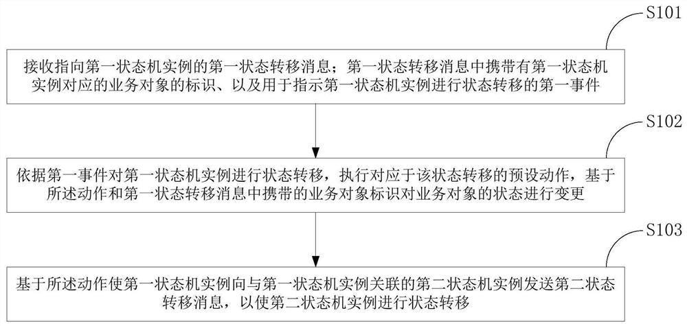
[0034] figure 1 is a schematic diagram of the main steps of the state machine linkage method according to the embodiment of the present invention.

[0035] Such as figure 1 As shown, the sta...


PUM


Abstract

The invention discloses a state machine linkage method and device, and relates to the technical field of computers. A specific embodiment of the method comprises the following steps: receiving a first state transition message pointing to a first state machine instance, wherein the first state transition message carries a service object identifier corresponding to the first state machine instance and a first event; performing state transition on the first state machine instance according to the first event, executing a preset action corresponding to the state transition, and changing the state of the service object based on the action and the service object identifier; causing the first state machine instance to send a second state transition message to a second state machine instance associated with the first state machine instance based on the action, wherein the second state transition message carries a service object identifier corresponding to the second state machine instance and a second event used for indicating the second state machine instance to perform state transition. According to the embodiment, state transition linkage between different state machine instances can be realized.

Description

technical field [0001] The present invention relates to the field of computer technology, in particular to a state machine linkage method and device. Background technique [0002] Finite State Machine (Finite State Machine, FSM), referred to as a state machine, is a mathematical model that represents finite states and behaviors such as transitions and actions between these states. In general, a finite state machine controls state transitions through the relationship between states, events, and actions. Using the state machine model to process the state transition in the business, you can see the state flow process more clearly in the form of a state topology diagram, and can avoid too many cumbersome if / else logic control statements in the code, making the code easy to maintain. [0003] The existing state machine implementation method generally follows the following process: first, define all the states involved in the business process as the state of the state machine; th...

Claims


Application Information

Patent Timeline
Patent Type & Authority Applications(China)
IPC IPC(8): G06F9/448G06F9/54
CPCG06F9/4498G06F9/542
Inventor 关梓骜黄栋谭伟
Owner BEIJING WODONG TIANJUN INFORMATION TECH CO LTD
Why Eureka
Eureka Blog
Learn More