


Quick Research
Generate reliable direction feasibility study reports for your R&D in just a few steps.

Technical Q&A
Discover and master advanced knowledge NOW. Basics, ideas, possibilities, all at once.

Find Solutions
As an expert in R&D theories, this can generate solutions to your technical problems instantly.

Evaluate Feasibility
Analyze your overall solution with one click, know your potential R&D risks in advance.

Monitor Landscape
Get weekly tech updates, stay abreast of the latest tech innovations and key insights.
Driving method and device of touch panel and touch display device
A technology of a touch panel and a driving method, which is applied in the input/output process of data processing, instruments, electrical digital data processing, etc., and can solve the problems of inability to realize real-time display, long response time of the touch display device, and touch response Long time and other problems, to achieve the effect of shortening the response time of the whole machine, shortening the touch response time, and shortening the time
- Summary
- Abstract
- Description
- Claims
- Application Information
AI Technical Summary
Problems solved by technology
Method used
Image

Examples
Embodiment 1
[0092] refer to Figure 4 , which shows a flow chart of a method for driving a touch panel according to an embodiment of the present invention, which may specifically include the following steps:
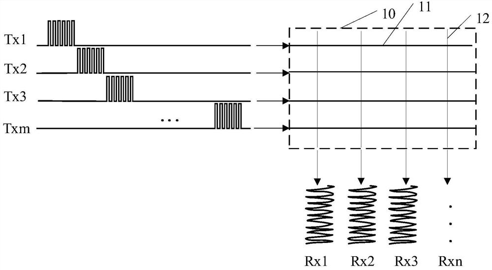
[0093] Step 401 , simultaneously input a first scanning signal to each of the first touch electrodes, and receive a first sensing signal of each of the second touch electrodes, so as to determine a suspected column according to the first sensing signal.
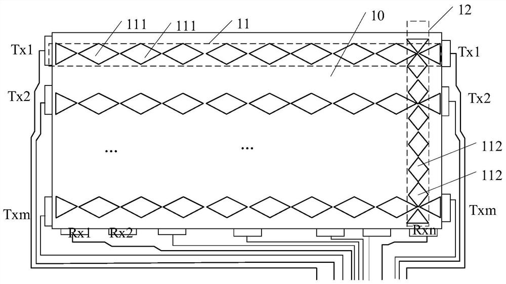
[0094] In the embodiment of the present invention, as Figure 5 and Image 6 As shown, the touch panel 20 includes a plurality of first touch electrodes 21 distributed along the row direction and a plurality of second touch electrodes 22 distributed along the column direction, and each first touch electrode 21 includes a plurality of first touch electrodes 21. Control sub-electrodes, each second touch electrode 22 includes a plurality of second touch sub-electrodes.
[0095] Wherein, the first touch electrode 21 is a touch drivi...
Embodiment 2
[0116] refer to Figure 8 , which shows a specific flowchart of a driving method for a touch panel according to an embodiment of the present invention, which may specifically include the following steps:
[0117] Step 801 , simultaneously input K consecutive first scanning signals to each of the first touch electrodes, and receive K first sensing signals of each of the second touch electrodes.
[0118] In the embodiment of the present invention, such as Figure 5 and Image 6 As shown, the touch panel 20 includes a plurality of first touch electrodes 21 distributed along the row direction and a plurality of second touch electrodes 22 distributed along the column direction, and each first touch electrode 21 includes a plurality of first touch electrodes 21. Control sub-electrodes, each second touch electrode 22 includes a plurality of second touch sub-electrodes. Wherein, the first touch electrodes 21 are touch driving electrodes, and the second touch electrodes 22 are touch s...
Embodiment 3
[0164] refer to Figure 9 , shows a structural block diagram of a driving device for a touch panel according to an embodiment of the present invention.
[0165] An embodiment of the present invention provides a driving device 900 for a touch panel. The touch panel includes a plurality of first touch electrodes distributed along a row direction and a plurality of second touch electrodes distributed along a column direction. The touch panel The drive unit 900 includes:
[0166] The suspicious column determination module 901 is configured to simultaneously input a first scanning signal to each of the first touch electrodes, and receive a first sensing signal of each of the second touch electrodes, so that according to the first sensing Signal identifies the suspect column;
[0167] The suspicious row determination module 902 is configured to simultaneously input a second scanning signal to each of the second touch electrodes, and receive a second sensing signal of each of the f...
PUM
 Abstract
Description
Claims
Application Information
 - R&D Engineer
- R&D Manager
- IP Professional
- Industry Leading Data Capabilities
- Powerful AI technology
- Patent DNA Extraction
Browse by: Latest US Patents, China's latest patents, Technical Efficacy Thesaurus, Application Domain, Technology Topic, Popular Technical Reports.
© 2024 PatSnap. All rights reserved.Legal|Privacy policy|Modern Slavery Act Transparency Statement|Sitemap|About US| Contact US: help@patsnap.com