Al technical title is built by PatSnap Al team. It summarizes the technical point description of the patent document.
A technology for biomass fuel and drying equipment, which is applied in drying solid materials, drying chambers/containers, non-progressive dryers, etc. The effect of improving work efficiency
Pending Publication Date: 2021-12-07
于坤
View PDF1 Cites 1 Cited by
Summary
Abstract
Description
Claims
Application Information
AI Technical Summary
This helps you quickly interpret patents by identifying the three key elements:
Problems solved by technology
Method used
Benefits of technology
Problems solved by technology
[0006] Aiming at the deficiencies of the prior art, the present invention provides a drying equipment for biomass fuel, which solves the problem that the device cannot prevent the drying of the straw material from being affected by moisture agglomeration when drying the straw, and improves the drying efficiency of the straw. High efficiency, preventing the incompletely dried straw material from accumulating on the arc-shaped stirring plate, effectively improving the practicability of the device, realizing the purpose of fully drying the internal straw, and making full use of the heat energy
Method used
Image
Click on the blue label to locate the original text in one second.
Reading with bidirectional positioning of images and text.
Examples
Embodiment 1
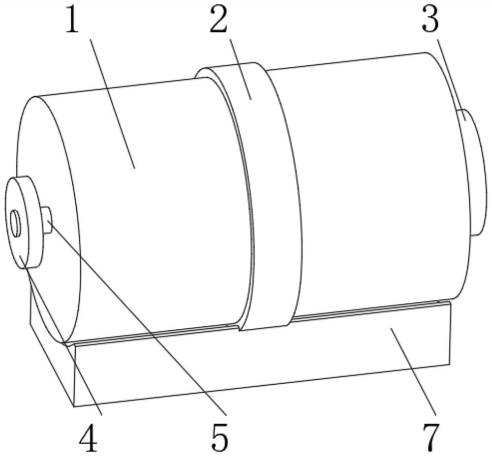
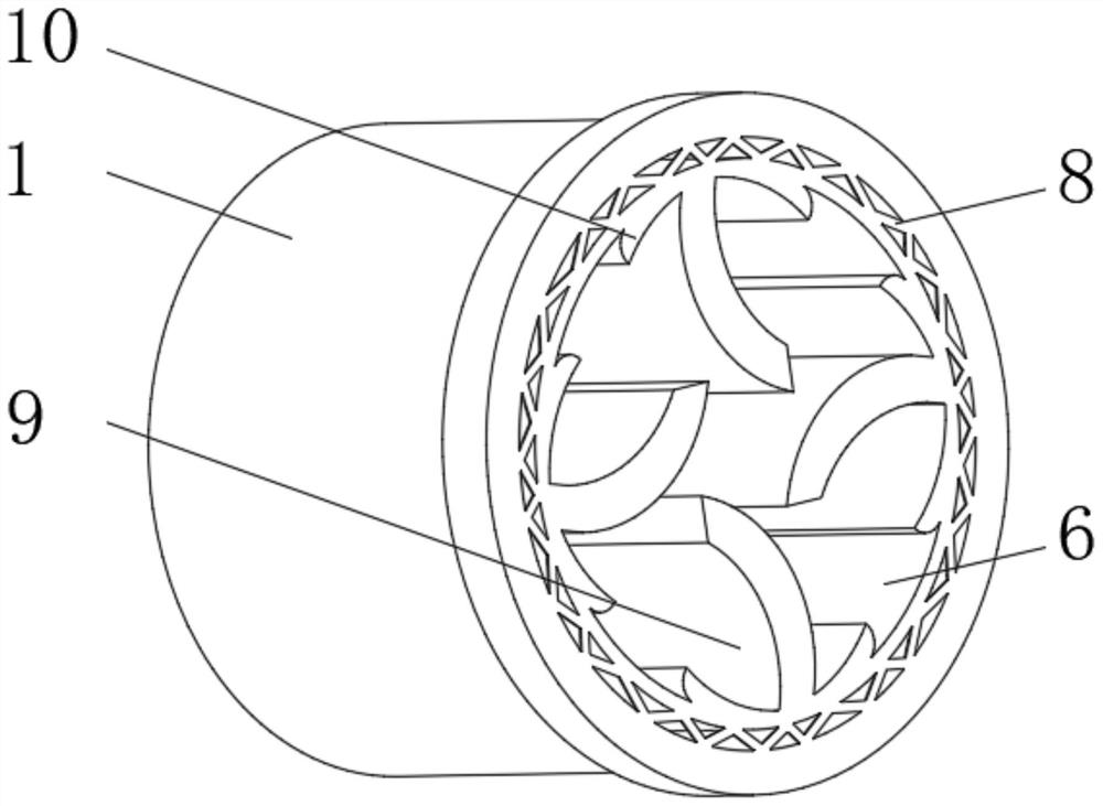
[0029] see Figure 1-4 , the present invention provides a technical solution: a drying equipment for biomass fuel, comprising an outer frame 1, a reinforcement frame 2 is installed on the outer side of the outer frame 1, a feed inlet 3 is opened on one side of the outer frame 1, and the outer frame 1 A drive motor 4 is installed on the side away from the feed port 3, the output shaft of the drive motor 4 is rotatably connected to a rotating shaft 5, and the end of the rotating shaft 5 away from the driving motor 4 is fixedly connected to a rotating frame 6, and the bottom of the outer frame 1 is fixedly connected to There is a base 7, a heating wire 8 is installed on the inner wall of the outer frame 1 close to the rotating frame 6, and a stirring device 9 is evenly installed on the inner wall of the rotating frame 6.
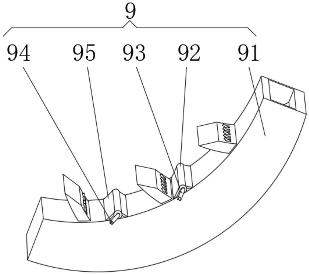
[0030] Stirring device 9 comprises arc-shaped stirring plate 91, and one side of arc-shaped stirring plate 91 is fixedly connected with rotating frame 6, and o...
Embodiment 2
[0036] see Figure 1-5 , the present invention provides a technical solution: on the basis of Embodiment 1, an ejection device 10 is evenly installed on the inner wall of the rotating frame 6 close to the position of the stirring device 9, and the ejection device 10 includes a semicircular frame 101, and one side of the semicircular frame 101 is connected to the The rotating frame 6 is fixedly connected, the inside of the semicircular frame 101 is fixedly connected with a spring 102 , and the end of the spring 102 away from the semicircular frame 101 is fixedly connected with an arc plate 103 .
[0037] An elastic rod 104 is fixedly connected to the inner wall of the semicircular frame 101 away from the spring 102 , and an elastic ball 105 is fixedly connected to the end of the elastic rod 104 away from the semicircular frame 101 .
[0038] When in use, the internal stalks are turned over with the rotating frame 6 and touch the extrusion arc plate 103, and the arc plate 103 is...
PUM
Abstract
The invention discloses drying equipment for biomass fuel. The drying equipment for the biomass fuel comprises an outer frame; a reinforcing frame is mounted on the outer side of the outer frame; a feeding opening is formed in one side of the outer frame; a driving motor is mounted on the side, far away from the feeding opening, of the outer frame; an output shaft of the driving motor is rotationally connected with a rotating shaft; a rotating frame is fixedly connected to the end, far away from the driving motor, of the rotating shaft; a base is fixedly connected to the bottom of the outer frame; an electric heating wire is mounted in the position, close to the rotating frame, on the inner wall of the outer frame; stirring devices are evenly mounted on the inner wall of the rotating frame; ejection devices are uniformly mounted in the positions, close to the stirring devices, on the inner wall of the rotating frame; and each stirring device comprises an arc-shaped stirring plate. The invention relates to the technical field of drying. According to the drying equipment for the biomass fuel, the purpose of stirring internal straw materials is achieved, the situation that the drying effect is affected due to the fact that the straw materials are moist and agglomerated is prevented, and the straw drying efficiency is effectively improved.
Description
technical field [0001] The invention relates to the technical field of drying, in particular to drying equipment for biomass fuel. Background technique [0002] Organic charcoal is a new type of energy. Its raw materials mainly include rice husk, peanut husk, cotton husk, corn cob, corn stalk, sorghum stalk, bean stalk, sawdust, sawdust, wood shavings, pine shell, coconut shell, etc. Straw is the most widely used raw material. At present, the straw production process includes crushing, drying, rod making, carbonization and other processes. There are many deep-processing products of straw, such as: biomass fuel, organic fertilizer ingredients, edible fungus culture medium, etc., all of which need to be chopped into segment, and then reprocessed, wherein the straw needs to be dried due to the high water content in the straw. [0003] For example, Chinese patent CN107906865A proposes a device for drying crop stalks, including a drying chamber, the outer upper side wall of the...
Claims
Application Information
Patent Timeline
Application Date:The date an application was filed.
Publication Date:The date a patent or application was officially published.
First Publication Date:The earliest publication date of a patent with the same application number.
Issue Date:Publication date of the patent grant document.
PCT Entry Date:The Entry date of PCT National Phase.
Estimated Expiry Date:The statutory expiry date of a patent right according to the Patent Law, and it is the longest term of protection that the patent right can achieve without the termination of the patent right due to other reasons(Term extension factor has been taken into account ).
Invalid Date:Actual expiry date is based on effective date or publication date of legal transaction data of invalid patent.