


Quick Research
Generate reliable direction feasibility study reports for your R&D in just a few steps.

Technical Q&A
Discover and master advanced knowledge NOW. Basics, ideas, possibilities, all at once.

Find Solutions
As an expert in R&D theories, this can generate solutions to your technical problems instantly.

Evaluate Feasibility
Analyze your overall solution with one click, know your potential R&D risks in advance.

Monitor Landscape
Get weekly tech updates, stay abreast of the latest tech innovations and key insights.
Metal shaft slotted hole forming equipment for high-end equipment manufacturing in metal processing factory
A processing plant and metal shaft technology, applied in metal processing equipment, metal processing, metal processing machinery parts, etc., can solve problems such as not having slotting function, inconvenient metal fixing, metal shaking, etc., to achieve automatic discharge at intervals, Realize the effect of manual blanking
- Summary
- Abstract
- Description
- Claims
- Application Information
AI Technical Summary
Problems solved by technology
Method used
Image

Examples
Embodiment 1
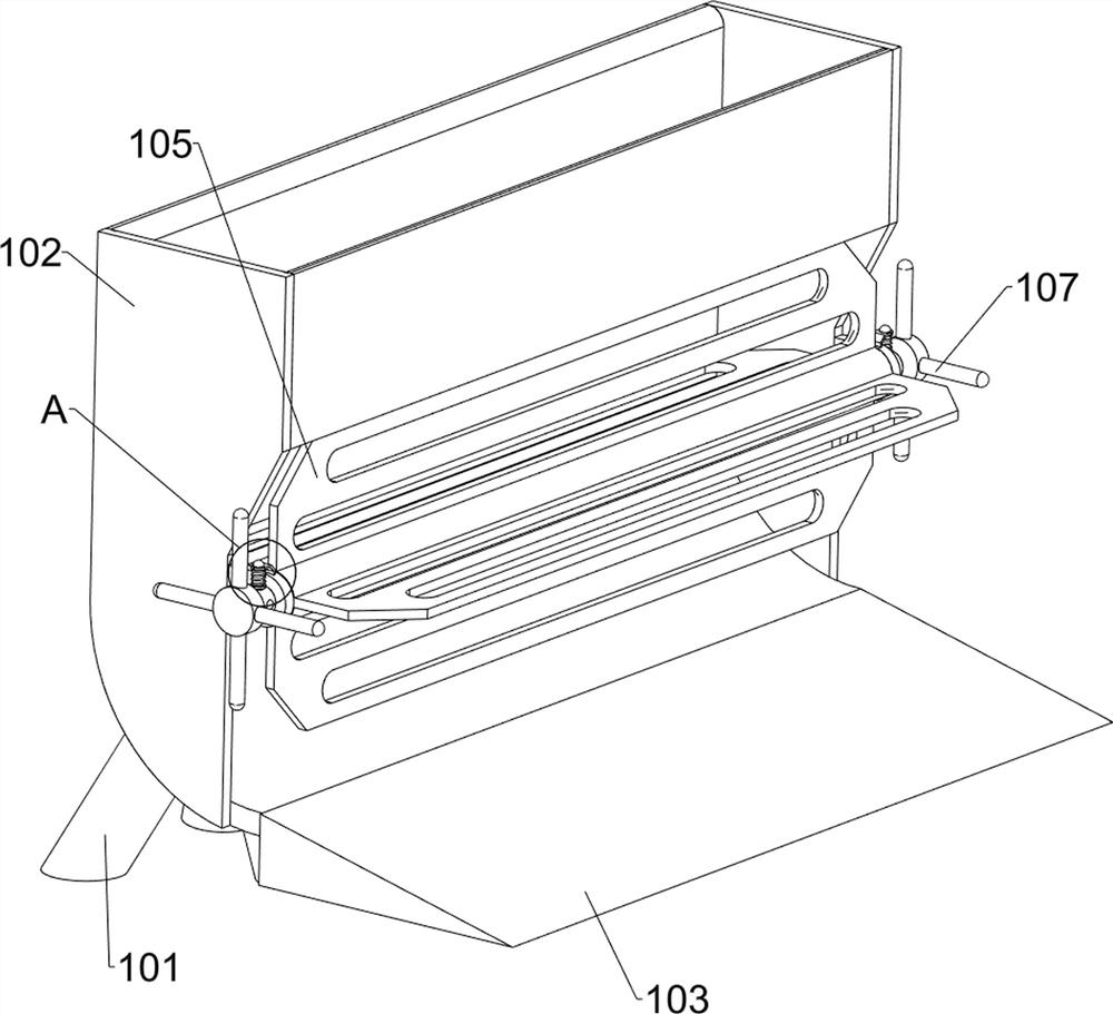
[0027] A metal shaft slotted hole equipment for high-end equipment manufacturing in metal processing plants, such as Figure 1-3 As shown, it includes a bottom plate 1, a placement seat 2, a fixed guide rail frame 3, a sliding guide rail frame 4, a connecting seat 5, an electric drilling machine 6, an adjustment mechanism 7 and a lifting mechanism 8, and the bottom plate 1 is provided with a placement seat 2 in the middle. 1 There are fixed rail frames 3 on the four sides of the top, sliding rail frames 4 are slidably connected between the fixed rail frames 3, and connecting seats 5 are slidably connected to the sliding rail frames 4, and electric drilling machines are arranged on the connecting seats 5 6. An adjustment mechanism 7 is provided on the sliding rail frame 4, and a lifting mechanism 8 is provided between the bottom plate 1 and the sliding rail frame 4.
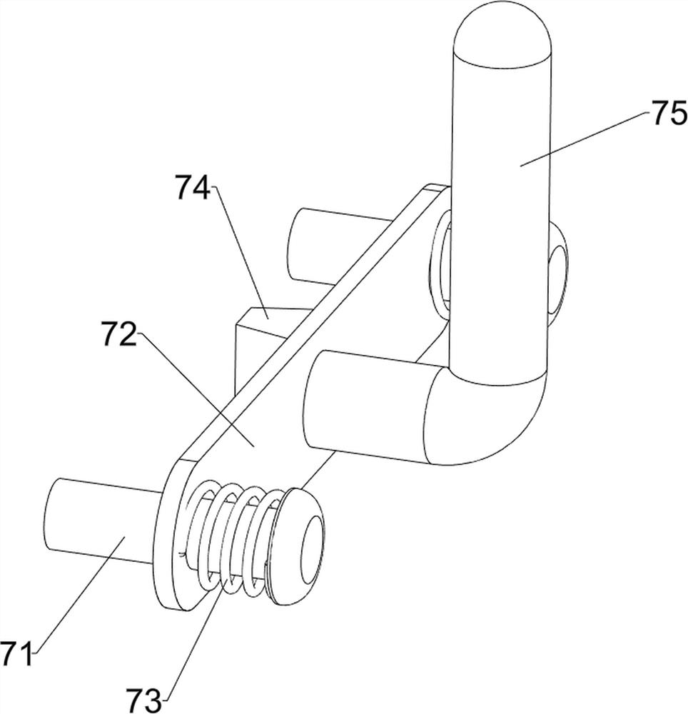
[0028] The adjustment mechanism 7 includes a first positioning rod 71, a sliding plate 72, a first back-moving ...
Embodiment 2
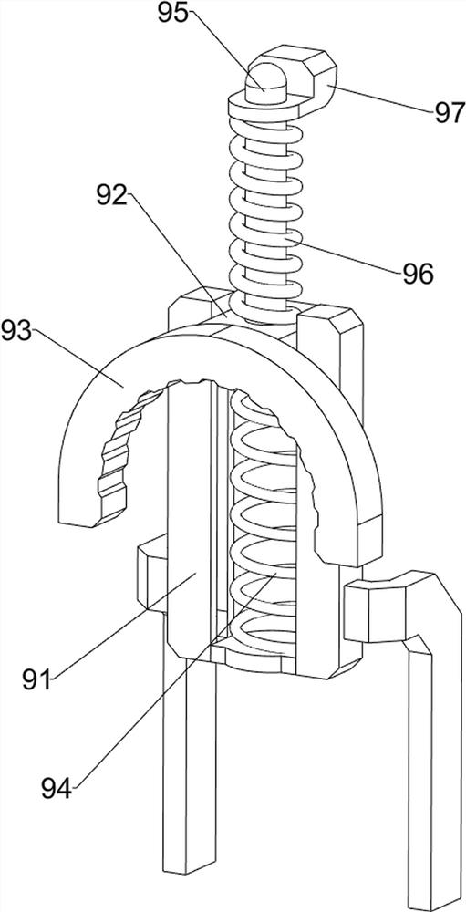
[0032] On the basis of Example 1, such as Figure 4-8As shown, a clamping mechanism 9 is also included, and the clamping mechanism 9 includes a guide rail seat 91, a sliding connection block 92, a clamping block 93, a third return spring 94, a second positioning rod 95, a support spring 96 and a pressure block 97, Base plate 1 front side top left and right sides are all provided with guide rail seat 91, all are slidably connected with sliding connection block 92 on the guide rail seat 91, all are provided with the 3rd back-moving spring between the bottom of sliding connection block 92 and guide rail seat 91 on the same side 94, the inside of the sliding connection block 92 is provided with clamping blocks 93, the top of the sliding connection block 92 is provided with a second positioning rod 95, and the second positioning rod 95 is slidably connected with a briquetting block 97, the briquetting block 97 and the sliding guide rail frame 4 connection, a support spring 96 is pr...
PUM
 Abstract
Description
Claims
Application Information
 - R&D Engineer
- R&D Manager
- IP Professional
- Industry Leading Data Capabilities
- Powerful AI technology
- Patent DNA Extraction
Browse by: Latest US Patents, China's latest patents, Technical Efficacy Thesaurus, Application Domain, Technology Topic, Popular Technical Reports.
© 2024 PatSnap. All rights reserved.Legal|Privacy policy|Modern Slavery Act Transparency Statement|Sitemap|About US| Contact US: help@patsnap.com