Charging system and charging management method for aged battery

A charging system and charging management technology, which is applied in different battery charging, battery circuit devices, battery load switching, etc., can solve the problems of not being a battery charging management system, low charging management efficiency, and lack of versatility, so as to avoid battery charging. The effect of maximizing voltage and charging benefits and reducing potential safety hazards

Pending Publication Date: 2021-12-03
SHENZHEN AUTEL INTELLIGENT AVIATION TECH CO LTD
View PDF0 Cites 1 Cited by
  • Summary
  • Abstract
  • Description
  • Claims
  • Application Information

AI Technical Summary

Problems solved by technology

[0005] Although the existing technology can manage the charging of aging batteries, it depends on the charger must be a smart charger, which does not have versatility, is not an ideal battery charging management syste

Method used


Image

  • Charging system and charging management method for aged battery
  • Charging system and charging management method for aged battery
  • Charging system and charging management method for aged battery

Examples


Embodiment 1

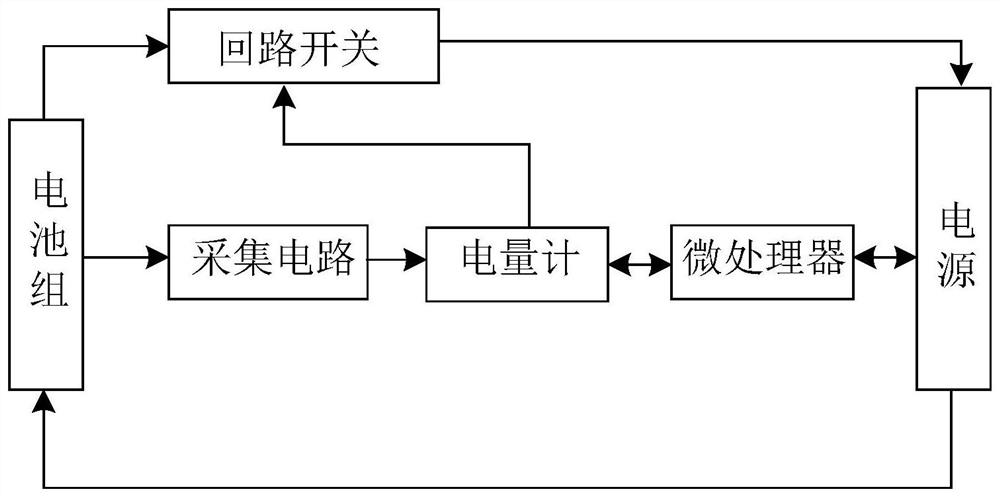
[0052] see figure 1 , this embodiment proposes a charging system for aging batteries, including:

[0053] Sampling circuit, the acquisition end of the sampling circuit is connected with the signal output end of the aging battery pack, and the output end of the sampling circuit outputs the battery signal in the charging of the aging battery pack collected by the sampling circuit;

[0054] A circuit switch, one connection end of the circuit switch is connected to the positive terminal of the aging battery pack;

[0055] Fuel gauge, the input terminal of the fuel gauge is connected to the output terminal of the sampling circuit, the control terminal of the fuel gauge is connected to the controlled terminal of the loop switch, the output terminal of the fuel gauge outputs the cycle signal generated by the fuel gauge according to the battery signal, and the fuel gauge control loop switch state;

[0056] The microprocessor is connected to the output terminal of the fuel gauge, recei...

Embodiment 2

[0084] see Figure 10 , On the basis of the above embodiments, this embodiment provides a charging management method for aging batteries, the charging management method runs in the charging system of any of the above embodiments; the charging management method includes steps:

[0085] S1. Determine the number of cycles of the fuel gauge in the charging state;

[0086] S2. If the number of cycles is not greater than the first threshold, maintain the original parameter charging.

[0087] It should be noted that the above embodiments are innovations of hardware circuits. This embodiment further combines computer programs on the basis of hardware circuits. In addition to having the technical effects of the above embodiments, it can also achieve more economical and effective treatment of aging batteries. charging management.

[0088] It should also be noted that after the charger is inserted, the battery enters the charging state, and the microprocessor reads the number of cycles...


PUM


Abstract

The invention belongs to the technical field of batteries, and provides a charging system for an aged battery, which comprises a sampling circuit, a loop switch, a voltameter and a microprocessor. Wherein the sampling circuit collects a battery signal during the charging of an aged battery pack; the loop switch is connected with the positive end of the aged battery pack; the output end of the voltameter outputs a circulation signal generated by the voltameter according to the battery signal to control the on-off state of the loop switch; and the microprocessor is connected with the output end of the voltameter, receives and processes the circulation signal, and controls the charging of the aged battery pack. Therefore, according to the circulation signal of the battery, the aging degree of the battery can be reflected, the charging of the battery can be dynamically adjusted, the overhigh battery voltage is avoided, and the potential safety hazard of the battery is greatly reduced. Meanwhile, charging adjustment is carried out on the battery based on the circulation signal of the battery, the voltage of the charger does not need to be adjusted, and therefore the requirement for intelligentization of the charger is lowered, and charging benefit maximization is achieved.

Description

technical field [0001] The invention relates to the technical field of batteries, in particular to a charging system for aging batteries. Background technique [0002] With the widespread use of lithium batteries, the problem of battery aging has become more and more prominent. Especially for the application of drone batteries, because the discharge rate of the battery is relatively large, the attenuation and aging of the battery will be more serious after multiple cycles. Especially for lithium batteries with multiple strings, when the battery ages, the voltage difference between the cells will accumulate and increase, and sometimes even charging equalization cannot make it equal. [0003] It can be said that battery aging is unavoidable, but how to manage the aging battery to balance the charge, prolong the service life of the battery, and reduce the safety risk of the battery is a problem that those skilled in the art have been facing. [0004] In the prior art, the cha...

Claims


Application Information

Patent Timeline
IPC IPC(8): H02J7/00
CPCH02J7/007184H02J7/007194H02J7/00714H02J7/0068H02J7/0047H02J7/005Y02E60/10
Inventor 秦威
Owner SHENZHEN AUTEL INTELLIGENT AVIATION TECH CO LTD
Why Eureka
Try Eureka