High-voltage electric appliance storage device with high safety

A high-voltage electrical and safety technology, applied in the substation/distribution enclosure, substation/switchgear cooling/ventilation, substation/switch layout details, etc. Electrical safety and other issues, to avoid failures and ensure the effect of normal work

Inactive Publication Date: 2021-12-03
安徽永汇新材料科技有限公司
View PDF0 Cites 0 Cited by
  • Summary
  • Abstract
  • Description
  • Claims
  • Application Information

AI Technical Summary

Problems solved by technology

[0003] However, the existing protective boxes for installing high-voltage electrical appliances have a simple structure, and water and dust are easy to enter, causing the high-voltage electrical appliances to malfunction, thereby reducing the safety of the high-voltage electrical appliances. In addition, when the high-voltage electrical appliances are energized and running, the external environment will easily lead to low stability of the high-voltage electrical appliances. poor, for this reason, the present invention proposes a high-safety high-voltage electrical appliance placement device that can solve the above-mentioned problems

Method used


Image

  • High-voltage electric appliance storage device with high safety
  • High-voltage electric appliance storage device with high safety
  • High-voltage electric appliance storage device with high safety

Examples


Embodiment 1

[0031] The present invention provides a technical solution: a high-voltage electric appliance placement device with high safety, including:
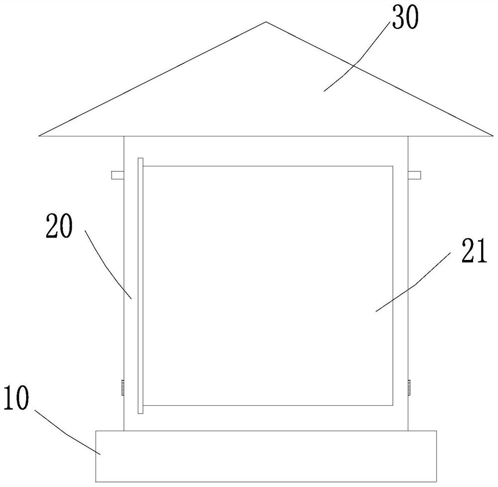
[0032] base 10;

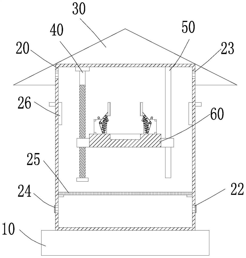
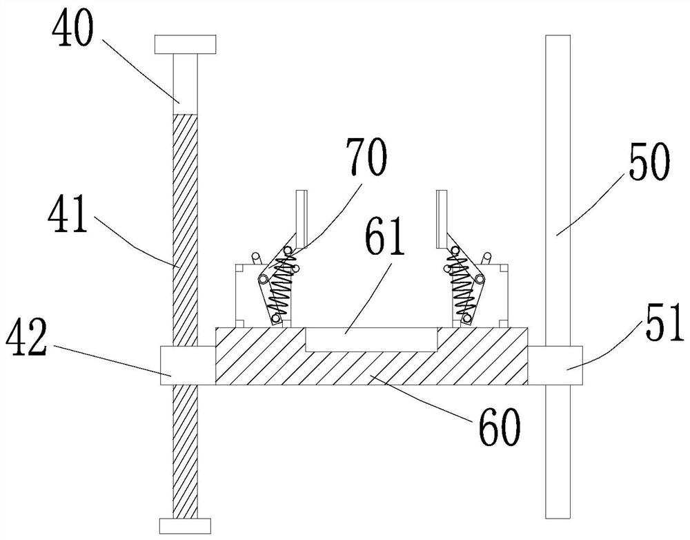
[0033] The housing 20, the housing 20 is arranged on the upper end of the base 10, the front side of the housing 20 is provided with an openable door 21, the housing 20 is vertically provided with a first rod body 40 and a second rod body 50, the first rod body 40 passes through The bearing assembly is rotatably connected to the inner top wall of the housing 20, the first rod body 40 is provided with a threaded section 41, the threaded section 41 is provided with a first moving seat 42, and the second rod body 50 is movably socketed with a second moving seat 51;

[0034] The carrying plate 60 is horizontally arranged inside the housing 20 and is located between the first rod body 40 and the second rod body 50 . One end of the carrying plate 60 is connected to the first moving seat 42 and the other end is connected to th...

Embodiment 2

[0037] On the basis of Embodiment 1, an exhaust port 23 is provided on the left and right sides of the top of the housing 20, an air inlet 22 is provided on the left and right sides of the bottom, and a first screen 24 is arranged on the air inlet 22; inside the housing 20 A support plate is provided, and a second screen 25 is horizontally arranged on the support plate, and the second screen 25 is located above the air inlet 22;

[0038] The top of the housing 20 is provided with a conical roof 30; the inner wall of the housing 20 is provided with a conduit 26, and the conduit 26 goes out of the housing 20 for passing through the wires in the transformer.

[0039]Specifically, the high-voltage electrical appliances will generate heat during operation, and gradually heat the air inside the casing 20, the air with a higher temperature in the casing 20 rises and is discharged from the top exhaust port 23, and the air with a lower temperature enters through the bottom air inlet 22 ...

Embodiment 3

[0041] On the basis of Embodiment 1 or Embodiment 2, the limit assembly 70 includes a vertical plate 71 arranged on the upper end of the bearing plate 60, and a rotating rod 72 is arranged on the vertical plate 71, and the rotating rod 72 passes through the vertical plate 71. Rod 72 is provided with one end rotating handle 75, and rotating handle 75 is provided with two groups of driving levers 751 that protrude forward, and the other end is hinged with first movable arm 73 and second movable arm 74, and first movable arm 73 extends upwards, and Connected with a butt plate 76, the top of the first movable arm is provided with a first fixed column 731 protruding forward, the second movable arm 74 extends downward, and the bottom of the second movable arm 74 is provided with a second fixed column protruding forward 741, the front side of the vertical plate 71 is provided with a tension spring 77, one end of the tension spring 77 is hooked on the first fixed column 731, and the ot...


PUM


Abstract

The invention discloses a high-voltage electric appliance storage device with high safety. The high-voltage electric appliance storage device comprises: a base; a shell arranged at the upper end of the base, wherein a door body capable of being opened and closed is arranged on the front side of the shell, a first rod body and a second rod body are vertically arranged in the shell, the first rod body is rotationally connected with the inner top wall of the shell through a bearing assembly, a threaded section is arranged on the first rod body, a first moving seat is arranged on the threaded section, and a second moving seat is movably connected to the second rod body in a sleeving mode; and a bearing plate horizontally arranged in the shell, wherein a containing groove is formed in the upper side of the bearing plate and used for containing a high-voltage electric appliance. The high-voltage electric appliance is firstly placed in the containing groove in the bearing plate, the high-voltage electric appliance is limited and clamped through a limiting assembly, so that the high-voltage electric appliance is kept stable on the bearing plate, and then the first rod body is rotated, so that the bearing plate moves upwards along the threaded section through the first moving seat to be away from the base, and is prevented from being eroded by an external environment water body, and the safety of the high-voltage electric appliance is effectively improved.

Description

technical field [0001] The invention relates to the technical field of high-voltage electrical protection, in particular to a high-safety high-voltage electrical device. Background technique [0002] High-voltage electrical appliances are equipment used to realize closing, breaking, protection, control, regulation and measurement in high-voltage lines. When high-voltage electrical appliances are used outdoors, they need to be installed in a protective box to avoid safety accidents. [0003] However, the existing protective boxes for installing high-voltage electrical appliances have a simple structure, and water and dust are easy to enter, causing the high-voltage electrical appliances to malfunction, thereby reducing the safety of the high-voltage electrical appliances. In addition, when the high-voltage electrical appliances are energized and running, the external environment will easily lead to low stability of the high-voltage electrical appliances. Poor, for this reaso...

Claims


Application Information

Patent Timeline
Patent Type & Authority Applications(China)
IPC IPC(8): H02B1/46H02B1/48H02B1/50H02B1/56H02B1/28H02B1/54
CPCH02B1/46H02B1/48H02B1/50H02B1/565H02B1/28H02B1/54
Inventor 许来褚娜娜时霞飞李华坤郭鹏生李凯范兴宇
Owner 安徽永汇新材料科技有限公司
Why Eureka
Try Eureka