
Cavity filter and communication equipment

A cavity filter and housing technology, applied in waveguide devices, electrical components, circuits, etc., can solve the problem that the volume and weight of communication equipment cannot increase linearly, and achieve lightweight, reduce overall height, and improve The effect of through rate

Active Publication Date: 2021-12-03
HUAWEI TECH CO LTD
View PDF6 Cites 0 Cited by
  • Summary
  • Abstract
  • Description
  • Claims
  • Application Information

AI Technical Summary

Problems solved by technology

However, considering the limited processing size of structural parts and the difficulty of field construction, the volume and weight of communication equipment cannot increase linearly, and the demand for miniaturization and light weight is becoming more and more urgent

Method used


Image

  • Cavity filter and communication equipment
  • Cavity filter and communication equipment
  • Cavity filter and communication equipment

Examples


Embodiment approach

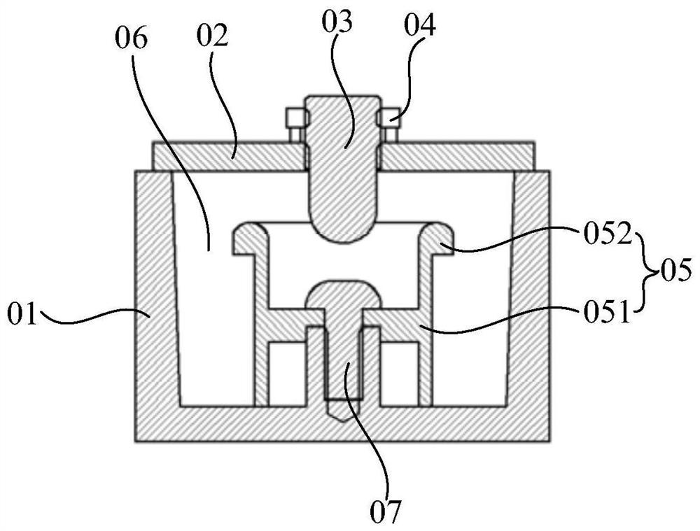
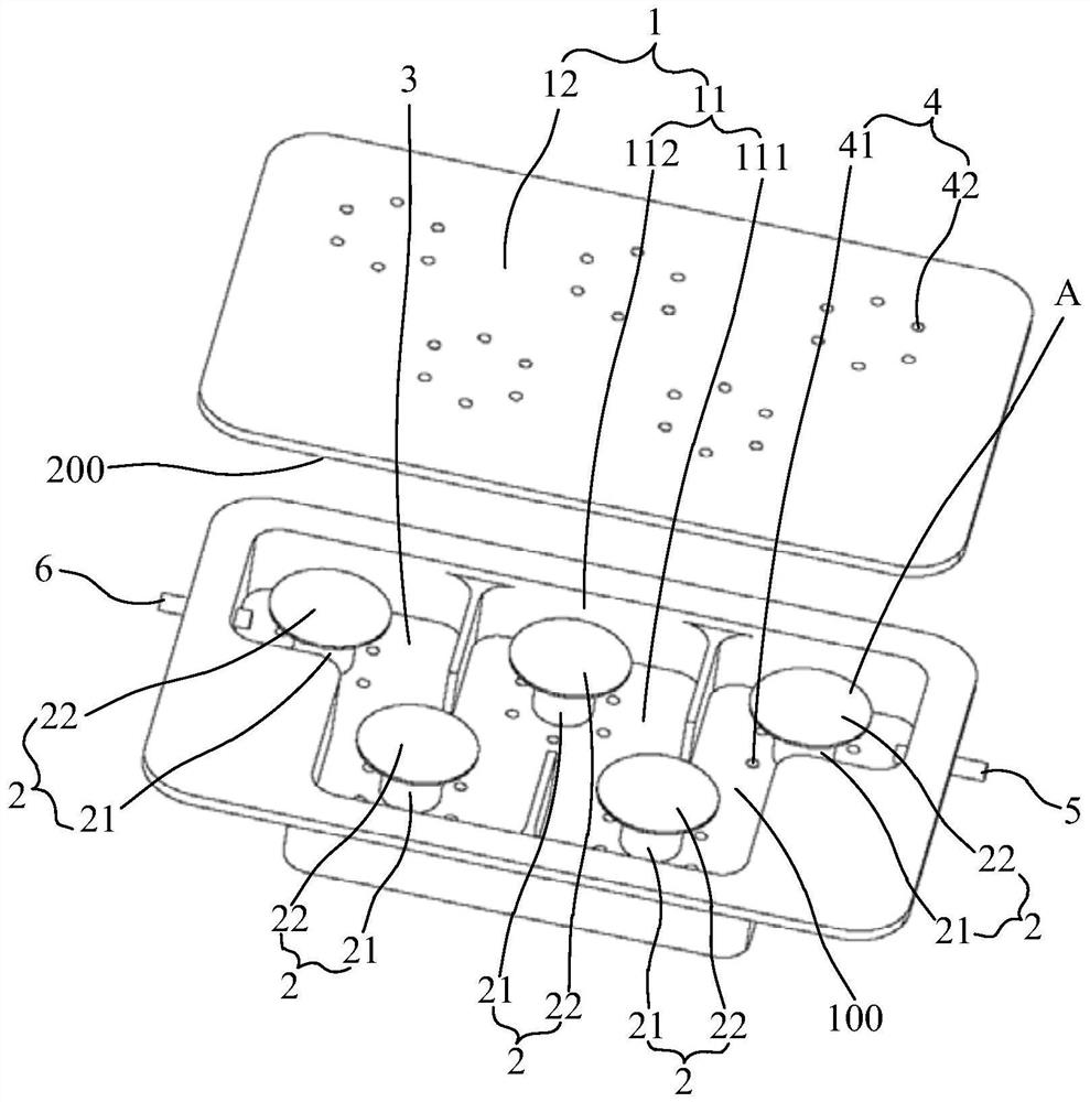
[0075] The first optional implementation, such as Figure 8 As shown, the first operating hole 41 is disposed on the housing wall where the first inner wall 100 is located. Optionally, an auxiliary operation hole 7 may also be provided on the suspension part A of the resonator plate 22 of at least one resonator 2, and the relative positional relationship between the auxiliary operation hole 7 and the first operation hole 41 satisfies that tools such as hooks can pass through The first operation hole 41 protrudes into the auxiliary operation hole 7 to drive the suspension portion A where the auxiliary operation hole 7 is located to bend toward the first inner wall 100 . Optionally, the projection of the auxiliary operation hole 7 on the plane where the first inner wall 100 is located coincides or partially coincides with the occupied area of ​​the first operation hole 41 on the first inner wall 100 .

[0076] In this way, tools such as thimbles and jacks can be used to extend ...


PUM


Abstract

The invention provides a cavity filter and communication equipment, relates to the technical field of communication equipment, can reduce the overall height, weight and size of the cavity filter, and can improve the first pass yield of the cavity filter. The cavity filter comprises a shell and at least one resonator, a closed resonant cavity is defined by the shell, and the shell comprises a first inner wall and a second inner wall which are opposite to each other. The at least one resonator is arranged in the resonant cavity, each resonator comprises a resonant column and a resonant disc, one end of the resonant column is fixed on the first inner wall, the other end of the resonant column extends towards the direction of the second inner wall, and the resonant disc is fixed on the end surface of one end, close to the second inner wall, of the resonant column; the disc surface of the resonance disc is opposite to the second inner wall and is spaced from the second inner wall; and the shell is provided with a first operation hole, and the first operation hole is used for enabling the suspension part of the resonance disc of at least one resonator to deform towards the direction of the first inner wall or the second inner wall. The cavity filter provided by the invention can be used for selecting the communication signal frequency.

Description

technical field [0001] The present application relates to the technical field of communication equipment, in particular to a cavity filter and communication equipment. Background technique [0002] In recent years, with the increase in the number of channels and the improvement in performance of communication equipment such as base stations, outdoor combiners, and tower amplifiers, the volume and weight of communication equipment have also increased. However, considering the limited processing size of structural parts and the difficulty of field construction, the volume and weight of communication equipment cannot increase linearly, and the demand for miniaturization and light weight is becoming more and more urgent. As a passive module commonly used in communication equipment, cavity filters can be used to select communication signal frequencies and filter out clutter or interference signals other than communication signal frequencies. Their size and weight directly affect ...

Claims


Application Information

Patent Timeline
Patent Type & Authority Applications(China)
IPC IPC(8): H01P1/208
CPCH01P1/208
Inventor 崔铮蓝祧汉方群梁丹潘超
Owner HUAWEI TECH CO LTD
Learn More