Strip steel surface image acquisition device for defect identification and use method thereof

A technology of surface image and acquisition device, which is applied in measurement device, optical testing of flaws/defects, material analysis by optical means, etc., can solve the problems of damaged strip surface image acquisition device, broken strip, strip damage, etc.

Pending Publication Date: 2021-12-03
CHANGZHOU UNIV
View PDF0 Cites 0 Cited by
  • Summary
  • Abstract
  • Description
  • Claims
  • Application Information

AI Technical Summary

Problems solved by technology

However, in the continuous production line of strip steel, due to mechanical errors in the unit, vibration and strip tension fluctuations, etc., the tension of the strip steel changes and even deviation occurs, which in turn causes damage and breakage of the strip steel. Strip steel with large tension changes will affect the accuracy of strip steel surface image acquisition, and strip steel after deviation or broken strip will damage the strip steel surface image acquisition device, especially the relatively fragile camera mechanism

Method used


Image

  • Strip steel surface image acquisition device for defect identification and use method thereof
  • Strip steel surface image acquisition device for defect identification and use method thereof
  • Strip steel surface image acquisition device for defect identification and use method thereof

Examples


Embodiment Construction

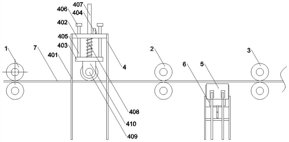
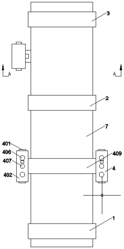
[0020] see Figure 1-Figure 5 , the present invention provides the following technical solutions: a strip surface image acquisition device for defect identification, including a pressure roller group one 1, a pressure roller group two 2, a pressure roller group three 3, the pressure roller group one 1, pressure roller group Roller group two 2 and pressure roller group three 3 are rollingly connected with strip steel 7, and the upper side of the strip steel 7 between the pressure roller group one 1 and pressure roller group two 2 is fixedly installed with a tension stabilization mechanism 4, so The tension stabilization mechanism 4 includes a leg one 401, the upper side of the leg one 401 is fixedly connected to both side end surfaces of a fixed plate 402, and a guide rod 405 and a slide rod 407 are slidably installed on the fixed plate 402, so The top surface of the fixed plate 402 is fixedly equipped with a travel switch 404, the top end of the guide rod 405 is fixedly connec...


PUM


Abstract

The invention belongs to the technical field of strip steel surface detection, and particularly relates to a strip steel surface image acquisition device for defect identification and a use method thereof. The strip steel surface image acquisition device comprises a first compression roller set, a second compression roller set and a third compression roller set, and the first compression roller set, the second compression roller set and the third compression roller set are connected with strip steel in a rolling mode; a tensioning degree stabilizing mechanism installed on the upper side of the strip steel comprises a first supporting leg, a fixing plate, a guide rod, a sliding rod, a travel switch, a limiting plate, a movable plate, a first spring, a fixing base, a tensioning roller, an outer cover plate and a photosensitive sensor, and a reflecting mechanism and a shooting mechanism are installed below the strip steel. The shooting mechanism comprises a third supporting leg, an outer shell, a motor, a driving gear, a driven gear, a rack, a camera, a shooting opening, a protective cover plate, a first connecting pin, a second spring and a second connecting pin, the tensioning roller can stabilize the tensioning degree of the strip steel within a small range to guarantee the detection effect, after the travel switch detects that the strip steel deviates, the camera can be retracted into the outer shell, and the camera is effectively isolated under the protection of a protective cover plate and the outer shell.

Description

technical field [0001] The invention belongs to the technical field of strip steel surface detection, and in particular relates to a strip steel surface image acquisition device for defect identification. Background technique [0002] At present, the surface inspection system based on machine vision has been successfully applied in various industries. As one of the strip surface defect detection methods, the machine vision detection system has an irreplaceable role. The imaging part of the strip steel surface quality inspection system is directly composed of a light source and an image sensor at a certain angle, that is, the image sensor is used to directly scan the upper and lower surfaces of the current strip steel to capture the strip steel image. For the acquisition of the image information of the lower surface of the steel strip, the image acquisition is usually carried out by directly shooting from the bottom to the top. However, in the continuous production line of ...

Claims


Application Information

Patent Timeline
IPC IPC(8): G01N21/89G01N21/88
CPCG01N21/8901G01N21/8914G01N21/8806G01N2021/8908G01N2021/8918G01N2021/8835
Inventor 张屹耿宗武
Owner CHANGZHOU UNIV
Why Eureka
Try Eureka