Multi-line material bonding machine device and implementation method thereof

A bonding machine and bonding technology, which is applied in the field of multi-line bonding machine devices, can solve the problems of slow efficiency, poor quality, and low production capacity, and achieve the effects of high bonding precision, fast bonding speed, and high product quality

Active Publication Date: 2021-12-03
华创天成(东阳市)电子有限公司
View PDF11 Cites 1 Cited by
  • Summary
  • Abstract
  • Description
  • Claims
  • Application Information

AI Technical Summary

Problems solved by technology

[0003]At present, most of the materials are accumulated and pasted manually, which has the problems of slow efficiency, poor quality and low production capacity

Method used


Image

  • Multi-line material bonding machine device and implementation method thereof
  • Multi-line material bonding machine device and implementation method thereof
  • Multi-line material bonding machine device and implementation method thereof

Examples


Embodiment 1

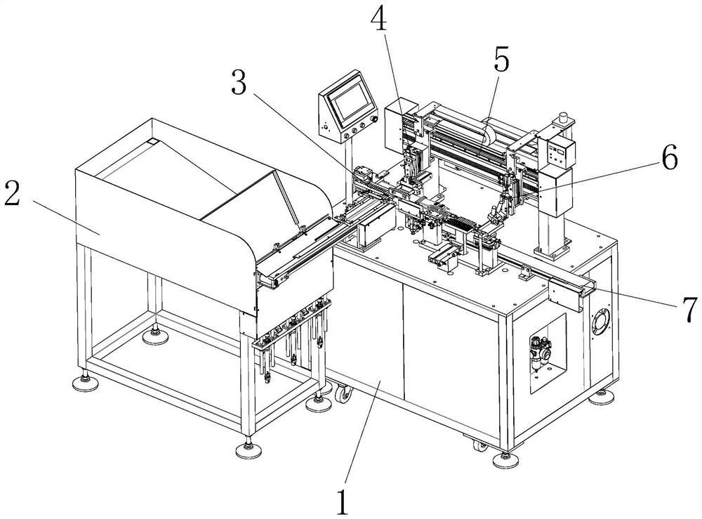
[0044] see Figure 1-9 , the present invention provides the following technical solutions: a multi-line adhesive machine device, including a frame 1, a manipulator 5 is connected above the frame 1, and a clamping mechanism 4 and a material bonding mechanism 6 are respectively connected to the output end of the manipulator 5 , the clamping mechanism 4 is located on one side of the sticking mechanism 6, and the top of the frame 1 is provided with a blanking mechanism 7 corresponding to the sticking mechanism 6 and an arrangement mechanism 3 corresponding to the clamping mechanism 4, and the frame 1 One side is provided with a feeding mechanism 2 corresponding to the arrangement mechanism 3, and the feeding mechanism 2, the arrangement mechanism 3, the clamping mechanism 4, the manipulator 5, the sticking mechanism 6 and the unloading mechanism 7 are all connected with the PLC controller signal.

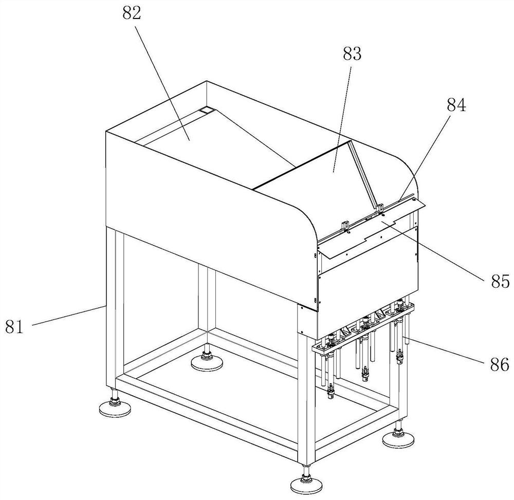
[0045]Specifically, the feeding mechanism 2 includes a feeding machine 8 and a feed...

Embodiment 2

[0068] see Figure 10 , the difference between this embodiment and Embodiment 1 is that: Specifically, two wrong material blocks 933 are provided on the wrong material component mounting seat 931. In this embodiment, three material troughs 935 are set as an example, one wrong material A material trough 935 is arranged on the material block 933 , two material troughs 935 are arranged on one material wrong block 933 , and a wrong material cylinder 934 corresponding to the two wrong material blocks 933 is provided below the wrong material component mounting seat 931 .

[0069] By adopting the above technical scheme, the feeding of single and double materials is realized; for circular materials, the upper material and the lower material are alternately bonded in dislocation, which can ensure the stability of the bonding. Therefore, in this embodiment, 10 The material is arranged into the lower layer material as an example. When two wrong material blocks 933 are fed at the same tim...


PUM


Abstract

The invention discloses a multi-line material bonding machine device. The multi-line material bonding machine device comprises a rack, a mechanical arm is connected to the upper portion of the rack, the output end of the mechanical arm is connected with a material clamping mechanism and a material bonding mechanism, the material clamping mechanism is located on one side of the material bonding mechanism, a discharging mechanism corresponding to the material bonding mechanism and an arranging mechanism corresponding to the material clamping mechanism are arranged above the rack, and a feeding mechanism corresponding to the arranging mechanism is arranged on one side of the rack. The invention further discloses an implementation method of the multi-line material bonding machine device. According to the multi-line material bonding machine device and the implementation method, automatic arrangement of materials and integration after arrangement are realized; the mechanical arm drives the material clamping mechanism to act to realize automatic carrying of materials, and the mechanical arm drives a gluing head to act to cooperate with a material seat lifting module to realize automatic gluing and bonding of the materials; and the multi-line material bonding machine device has the characteristics of being high in quality of bonded products, high in bonding speed, high in bonding precision, stable in productivity and capable of saving labor cost.

Description

technical field [0001] The invention belongs to the technical field of neodymium-iron-boron material bonding, and in particular relates to a multi-line bonding machine device and a realization method thereof. Background technique [0002] NdFeB materials need to be cut into small squares or small discs, so multi-line machines need to be used for processing. Multi-line machining needs to improve efficiency and production capacity, and multiple individual product (square or round) materials need to be combined. A large square, and then multi-line machining can improve production efficiency. [0003] At present, most of the materials are accumulated and pasted manually, which has the problems of slow efficiency, poor quality and low production capacity. [0004] Therefore, there is an urgent need for a multi-line binder device that can replace manual labor to solve the above technical problems. Contents of the invention [0005] The purpose of the present invention is to pr...

Claims


Application Information

Patent Timeline
IPC IPC(8): B65G47/82B65G47/26B65G47/90B65G47/04B05C5/02B05C13/02
CPCB65G47/82B65G47/261B65G47/90B65G47/04B05C5/0208B05C13/02Y02P70/50
Inventor 王华
Owner 华创天成(东阳市)电子有限公司
Why Eureka
Try Eureka