
Mechanical arm kinematics self-calibration method based on binocular vision

A technology of binocular vision and manipulators, which is applied in manipulators, program-controlled manipulators, manufacturing tools, etc., can solve problems such as high cost, manual participation, and cumbersome calibration process, achieve accurate readings, reduce the impact of absolute positioning accuracy, and search wide range of effects

Pending Publication Date: 2021-12-03
HENAN UNIVERSITY
View PDF0 Cites 0 Cited by
  • Summary
  • Abstract
  • Description
  • Claims
  • Application Information

AI Technical Summary

Problems solved by technology

[0003] Aiming at the problems that the existing kinematics calibration process of the manipulator is cumbersome, the cost is too high and manual participation is required, the present invention proposes a binocular vision-based self-calibration method for the kinematics of the manipulator. The mixed model parameters are used for parameter identification, which reduces the influence of non-geometric factors on the positioning accuracy of the end, simplifies the redundancy of the calibration system, and realizes the automation of the entire calibration process. The servo motor model is established, and the least square method is used to optimize the model, which further improves the performance of the manipulator. Absolute Positioning Accuracy

Method used


Image

  • Mechanical arm kinematics self-calibration method based on binocular vision
  • Mechanical arm kinematics self-calibration method based on binocular vision
  • Mechanical arm kinematics self-calibration method based on binocular vision

Examples


Embodiment Construction

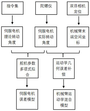
[0052] The embodiment of the present invention will be described in detail below, an example of a binding method based on a binocular visual manipulation figure 1 Down. The embodiments described below are illustrative of the embodiments described with reference to the accompanying drawings, and is not to be construed as limiting the invention.

[0053] Collecting the position information of the robot arm, the engine theory rotation angle, the actual rotation angle of the servo motor, the acquisition method is as follows:

[0054]Optionally, according to the mechanical structure of the robot arm Determines the range of each servo motor command, 50 sets of data is quoted, for any N axis rigid body arm. 50 sets of instructions are randomly generated, each set of instructions contain N servo rotation information, convert the instruction to an angle as a servo motor theoretical rotation angle.

[0055] During the execution of the instruction, the robot uses the gyroscope to collect the...


PUM


Abstract

The invention relates to the field of self-adaptive control, in particular to a mechanical arm kinematics self-calibration method based on binocular vision. Firstly, data are collected, and the tail end position information of a mechanical arm and the actual rotation angle and the theoretical rotation angle of each joint of the mechanical arm are obtained through a binocular camera. Then, the DH theory and the hand-eye calibration theory are fused, and a mechanical arm kinematics hybrid model is established. The model is trained by using a multi-population self-adaptive difference algorithm, and parameters of the hybrid model are solved. Finally, each servo motor model is established through a polynomial fitting method, and polynomial parameter solving and compensation prediction are conducted by using a least square method. According to the hybrid model and the servo motor models provided by the invention, the influence of geometric errors on the mechanical arm can be greatly reduced, and more practical model parameters can be calculated. A mechanical arm base coordinate system needed in the hand-eye calibration process does not need to be additionally established through a demonstrator, and automation of the whole calibration process can be achieved on the premise that absolute positioning precision is guaranteed.

Description

Technical field [0001] The present invention relates to the field of adaptive control, and more particularly to a binding method based on bicomputer visual mechanical arm motion self-standard. Background technique [0002] In recent years, mechanical arm control has played an important role in automotive manufacturing, fruit picking, pipeline operations, surgery, etc., and is of great significance to industrial, agriculture and manufacturing development. Most multi-freedom robotic arm systems are essentially a semi-closed control structure that can only accurately control the position of the joint servo motor, and the relationship between the position of the motor position and the actuator position of the mechanical arm is determined by kinematics. At present, the impact of mechanical arms produced by robotic arm manufacturers at home and abroad cannot guarantee the absolute fit of each module, and the mechanical arm is worn in the process of motor wear, external noise and other ...

Claims


Application Information

Patent Timeline
IPC IPC(8): B25J9/16B25J19/00
CPCB25J9/1692B25J9/1697B25J19/0095
Inventor 陈立家范贤博俊王赞代震王晨露王敏汪钇成许世文李孟伟
Owner HENAN UNIVERSITY
Learn More