
Multi-angle bending machine for electrical cabinet manufacturing

A multi-angle, bending machine technology is applied in the field of electrical cabinet production, which can solve the problems of low production efficiency, poor bending effect, and inability to adjust the bending angle of electrical cabinet profiles according to needs.

Pending Publication Date: 2021-12-03
肖丽芳
View PDF5 Cites 0 Cited by
  • Summary
  • Abstract
  • Description
  • Claims
  • Application Information

AI Technical Summary

Problems solved by technology

[0004] Based on this, it is necessary to address the above problems and propose a multi-angle bending machine for electrical cabinet manufacturing that can automatically bend the electrical cabinet profiles and adjust the bending angle of the electrical cabinet profiles according to requirements, so as to solve the problems in the above background technology. Problems that the bending angle of the electrical cabinet profile cannot be adjusted according to the demand, the production efficiency is low, and the bending effect is poor

Method used


Image

  • Multi-angle bending machine for electrical cabinet manufacturing
  • Multi-angle bending machine for electrical cabinet manufacturing
  • Multi-angle bending machine for electrical cabinet manufacturing

Examples


Embodiment 1

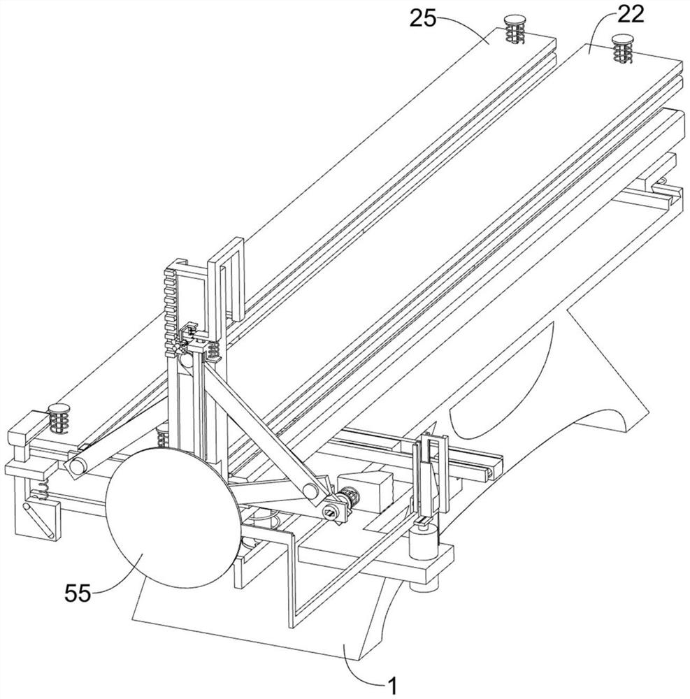
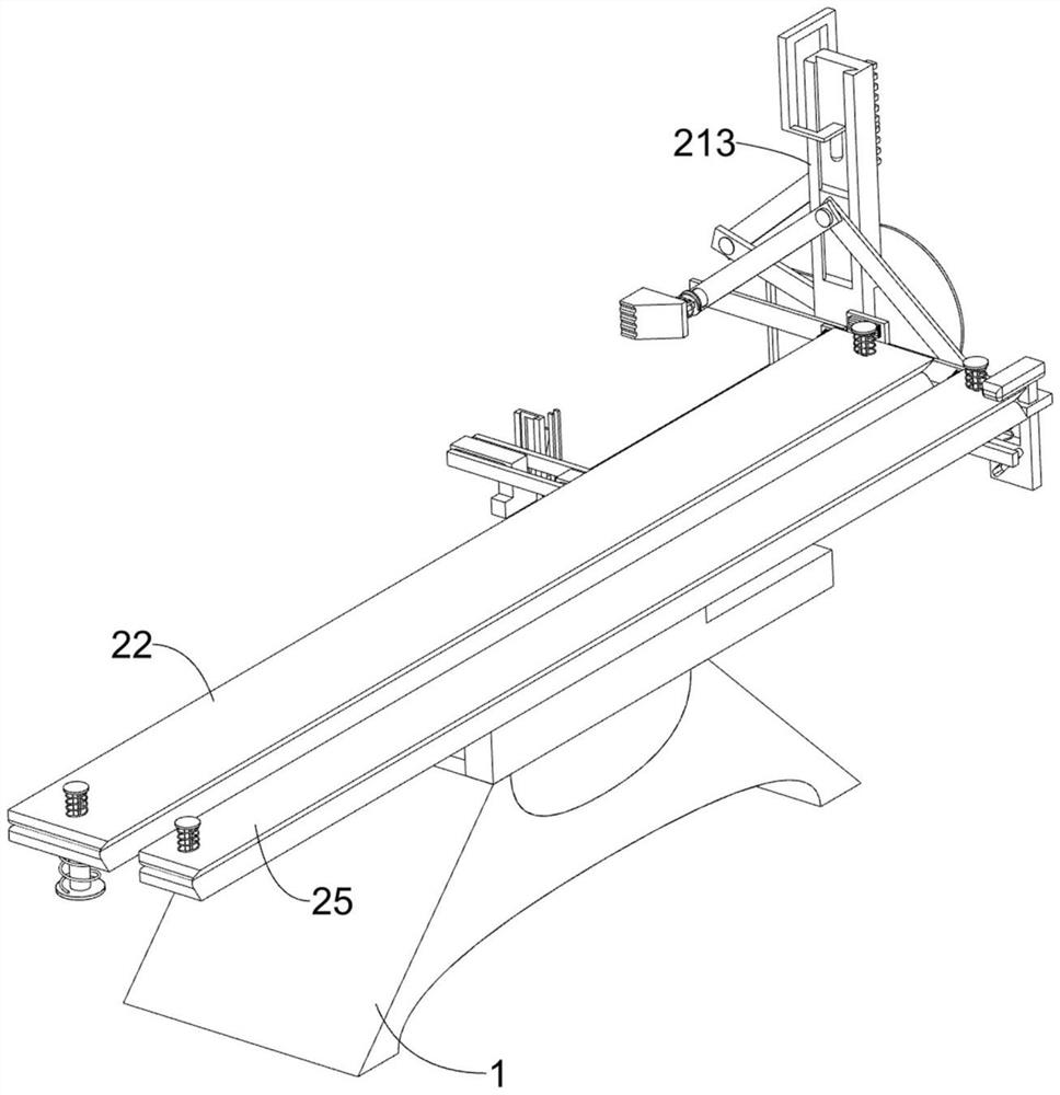
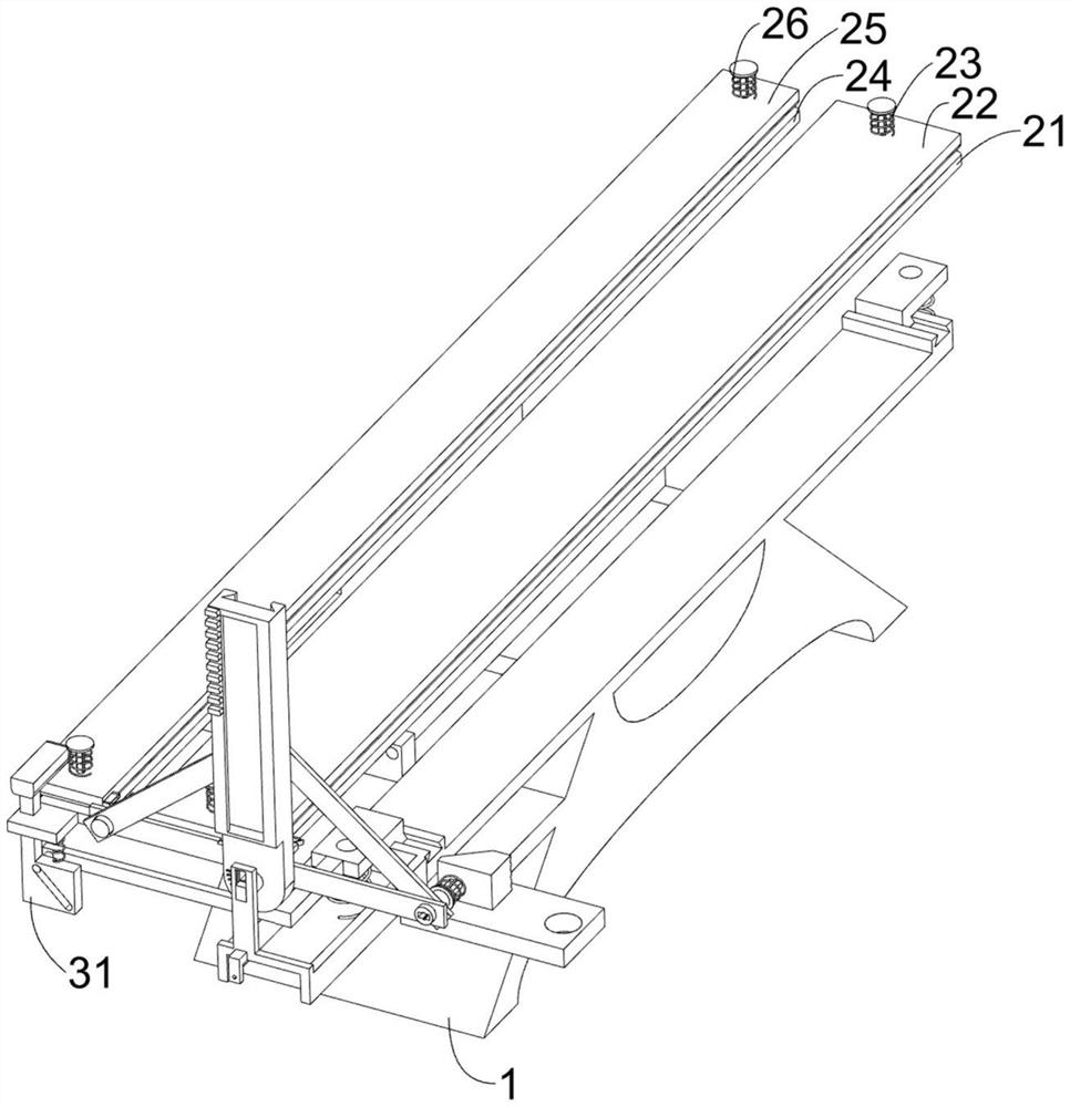
[0030] A multi-angle bending machine for making electrical cabinets, such as Figure 1-12 As shown, it includes a support chassis 1, a limit assembly 2, a bending adjustment assembly 3, a push assembly 4, a termination assembly 5, and a limit clamp assembly 6. The limit assembly 2 is arranged on the support chassis 1, and the bending The adjustment assembly 3 is arranged on the limit assembly 2, the bending adjustment assembly 3 is used to make the equipment suitable for electrical cabinet profiles of different thicknesses, the push assembly 4 is arranged on the support chassis 1, and the termination assembly 5 is arranged on the limit assembly 2 Above, the limit clamp assembly 6 is arranged on the limit assembly 2 , and the limit clamp assembly 6 is used to prevent the third limit plate 24 from being displaced from the electrical cabinet profile on the first limit plate 21 .

[0031]The limiting assembly 2 includes a first limiting plate 21, a second limiting plate 22, a firs...

Embodiment 2

[0042] On the basis of Example 1, such as Figure 11-12 As shown, it also includes an adjustment assembly 7, the adjustment assembly 7 is arranged on the limit assembly 2, the adjustment assembly 7 is used to adjust the bending angle of the profile of the electrical cabinet according to the demand, the adjustment assembly 7 includes a third swing plate 71, a fourth Swing plate 72, block 73, adjustment push frame 74, the ninth spring 75, card frame 76 and the tenth spring 77, the third swing plate 71 is connected in rotation on the sliding support frame 27, and the third swing plate 71 is used to indicate The scale value on the swing slide rail frame 212, the third swing plate 71 is connected with the fourth swing plate 72 in rotation, the fourth swing plate 72 is used to drive the third swing plate 71 to swing, the fourth swing plate 72 and the first adjustment The sliding frame 51 is rotatably connected, and the swing rail frame 212 is distributedly connected with blocks 73, ...


PUM


Abstract

The invention relates to the field of electrical cabinet production, in particular to a multi-angle bending machine for electrical cabinet manufacturing. The multi-angle bending machine comprises a supporting bottom frame, a limiting assembly, a bending adjusting assembly, a pushing assembly, a terminating assembly and the like, wherein the limiting assembly is arranged on the supporting bottom frame, the bending adjusting assembly is arranged on the limiting assembly, the pushing assembly is arranged on the supporting bottom frame, and the terminating assembly is arranged on the limiting assembly. According to the multi-angle bending machine, through cooperation of a clamping frame and a device on the clamping frame, the clamping frame and the device on the clamping frame move to change the position of a second adjusting sliding frame, so that the movement stroke of a first sliding block and a device on the first sliding block is changed,the bending angle of the electrical cabinet profile is changed, and the angle of a third swing plate pointing to two times of the scale on a swing slide rail frame is the bending angle of a electrical cabinet section bar by a thrust frame, so that the effect of adjusting the bending angle of the electrical cabinet section bar according to requirements is achieved.

Description

technical field [0001] The invention relates to the field of electric cabinet production, in particular to a multi-angle bending machine for making electric cabinets. Background technique [0002] The electrical cabinet is a cabinet made of steel to protect the normal operation of components. Its function is to distribute electric energy to various load parts, and to provide power-off protection when the circuit is short-circuited, overloaded and leakage. The electrical cabinet is widely used. It is mainly used in the chemical industry, environmental protection industry, power system, etc. The working area of ​​the electrical cabinet is mostly set in an outdoor open-air environment. After the bending treatment, the welding of the whole frame is carried out. [0003] At present, the method of bending the profile of the electrical cabinet usually uses a bending machine, but the bending angle of the profile is not easy to adjust, and it is often necessary to perform complex an...

Claims


Application Information

Patent Timeline
Patent Type & Authority Applications(China)
IPC IPC(8): B21D7/06B21D7/16
CPCB21D7/06B21D7/16
Inventor 肖丽芳
Owner 肖丽芳
Learn More