
Bending mechanism for solenoid valve coil pin

A technology of solenoid valve coil and bending mechanism, applied in the field of bending mechanism, can solve the problems of low work efficiency, increased price of solenoid valve, slow speed, etc., and achieve the effect of improving work efficiency

Pending Publication Date: 2022-04-05
中山市博胜机电设备有限公司
View PDF0 Cites 0 Cited by
  • Summary
  • Abstract
  • Description
  • Claims
  • Application Information

AI Technical Summary

Problems solved by technology

The traditional way is to manually use hardware tools to realize the bending operation of the coil pins sleeved on the valve body, which has slow speed and low work efficiency, which seriously affects the overall installation and operation of the solenoid valve.
It also increases the production cost per unit time, which eventually leads to an increase in the price of the solenoid valve, which is not conducive to the later market competition

Method used


Image

  • Bending mechanism for solenoid valve coil pin
  • Bending mechanism for solenoid valve coil pin
  • Bending mechanism for solenoid valve coil pin

Examples


Embodiment Construction

[0024] In order to make the purpose, technical solutions and advantages of the embodiments of the present invention clearer, the technical solutions in the embodiments of the present invention will be clearly and completely described below in conjunction with the drawings in the embodiments of the present invention. Obviously, the described embodiments It is a part of embodiments of the present invention, but not all embodiments. Based on the embodiments of the present invention, all other embodiments obtained by persons of ordinary skill in the art without creative efforts fall within the protection scope of the present invention.

[0025] In the description of the present invention, it should be noted that the terms "center", "upper", "lower", "left", "right", "vertical", "horizontal", "inner", "outer" etc. The indicated orientation or positional relationship is based on the orientation or positional relationship shown in the drawings, and is only for the convenience of desc...


PUM


Abstract

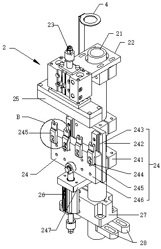
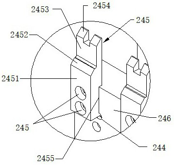
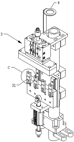
The invention relates to the technical field of electromagnetic valve coil pin welding, in particular to an electromagnetic valve coil pin bending mechanism which comprises a first 45-degree bending assembly and a second 90-degree bending assembly which are installed on a workbench of coil welding equipment. The first 45-degree bending assembly and the second 90-degree bending assembly are arranged at welding grooves in the periphery of a rotary disc on the workbench. The first 45-degree bending assembly and the second 90-degree bending assembly are the same in structure. The first 45-degree bending assembly comprises a guide cylinder, a product positioning air cylinder is installed on the upper portion of the guide cylinder, and a cylinder shaft of the product positioning air cylinder is connected with a horizontal positioning block. A first clamp component is arranged in the middle of the guide cylinder. A bending air cylinder assembly is arranged on the lower portion of the guide cylinder. The electromagnetic valve coil pin bending device has the advantages that the electromagnetic valve coil pin can be automatically bent, tin adding and welding on the electromagnetic valve coil pin in the subsequent working procedure are facilitated, line production is formed, and the working efficiency is greatly improved.

Description

technical field [0001] The invention relates to the technical field of solenoid valve coil pin welding, in particular to a bending mechanism for solenoid valve coil pins. Background technique [0002] Solenoid valve is an automatic basic component used to control fluid, which belongs to actuator and is not limited to hydraulic and pneumatic. Different solenoid valves play a role in different positions of the control system, and the most commonly used ones are check valves, safety valves, directional control valves, speed regulating valves, etc. There is a closed cavity in the solenoid valve, and there are through holes in different positions. Each hole is connected to a different oil pipe. There is a piston in the middle of the cavity, and two electromagnets on both sides. On the other hand, different oil discharge holes are opened or closed by controlling the movement of the valve body, while the oil inlet hole is normally open, the hydraulic oil will enter different oil d...

Claims


Application Information

Patent Timeline
IPC IPC(8): B21F1/00
Inventor 申健罗明华张文
Owner 中山市博胜机电设备有限公司
Learn More