
Bending device for seat framework

A bending device and seat frame technology, applied in the field of cushion processing, can solve the problems of no equipment processing, difficult automatic equipment processing, affecting the aesthetics and comfort of the seat, and achieve the effect of convenient support and fixing, and convenient use

Inactive Publication Date: 2021-03-19
安庆中巨机电科技有限公司
View PDF0 Cites 0 Cited by
  • Summary
  • Abstract
  • Description
  • Claims
  • Application Information

AI Technical Summary

Problems solved by technology

[0003] The car seat frame refers to the internal support frame of the car seat, which is usually welded by steel materials. The seat frame must be able to withstand a certain load, and the overall comfort of the seat is also closely related to the structure of the seat frame. , the buttock support structure of the existing seat frame is usually composed of multiple S-shaped springs distributed in an array, which only plays a simple supporting effect, and its structural firmness, stability and comfort are relatively general, and because The pressure of the buttocks on the seat is not uniform, and it is easy to cause the deformation of the spring after a long time of use. The deformation of the spring in the middle part is particularly serious, which affects the overall aesthetics and comfort of the seat. There are fewer contact positions on the head of the person, and the effect is not too great
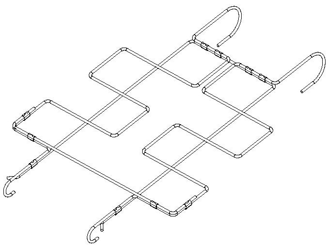
[0004] In view of this, the existing problems are studied and improved. In addition to the main frame, the steel wire is generally processed into a variety of small frames of different specifications, such as figure 1 As shown, the combination of the small frame and the main frame can provide convenient, reliable, and comfortable support for the occupants. There is currently no suitable equipment for processing the small frame formed by bending or bending steel wires, and due to its There are so many types that it is difficult to complete processing with existing automation equipment

Method used


Image

  • Bending device for seat framework
  • Bending device for seat framework
  • Bending device for seat framework

Examples


Embodiment Construction

[0028] Combine below Figure 2 to Figure 20 , the present invention is described in further detail.

[0029] In this case, more power units or drive units are involved to drive other parts to move, and the specific structure is not given in detail, because common drive units such as slide rails, screw nuts, and cylinders can be used. The content of the invention is more concise, and only the function of each power unit or drive unit is described below.

[0030] At the same time, in the following content, the advantages of the structures in some solutions have been mentioned above, so in the subsequent description of the solution, only the solution itself will be described, and the advantages or beneficial effects of the solution will not be repeated.

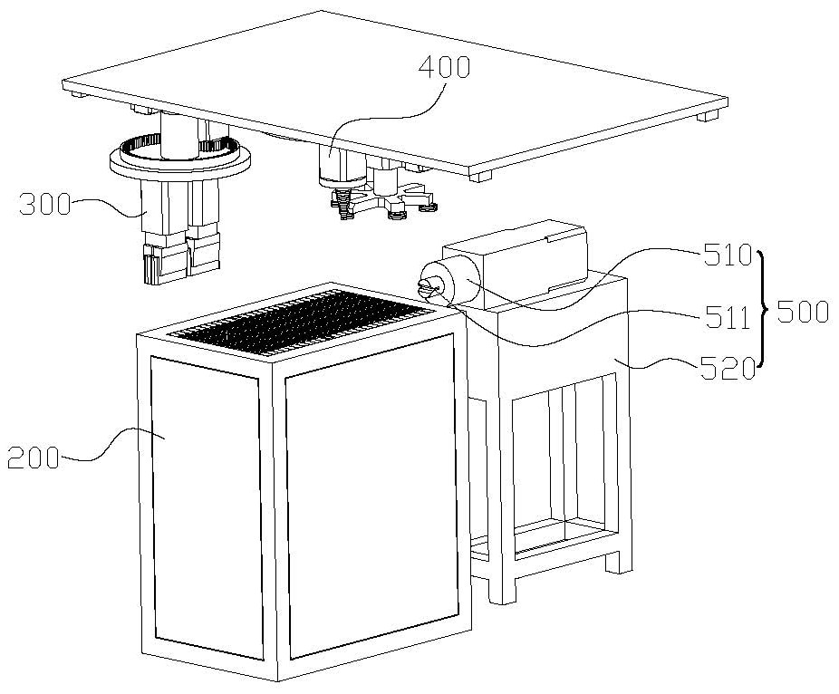
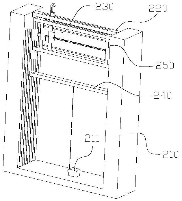
[0031] refer to Figure 2-Figure 8 , the present invention discloses a bending device for a seat frame, comprising a supporting unit 200, a bending unit 400 and a bending unit 300, the supporting unit 200 is used to support th...


PUM


Abstract

The invention particularly relates to a bending device for a seat framework. The bending device comprises a supporting unit, a curving unit and a bending unit, wherein the supporting unit is used forsupporting a steel wire to be bent and fixing the steel wire; the bending unit and the curving unit are arranged above the supporting unit; the bending unit is used for bending the steel wire on the upper surface of the supporting unit according to a certain angle; and the curving unit is used for curving the steel wire on the upper surface of the supporting unit according to a certain curvature radius. By arrangement of the supporting unit, the steel wire can be conveniently supported and fixed; meanwhile, by arrangement of the curving unit and the bending unit, the curving unit can curve thesteel wire, and the bending unit is used for bending the steel wire into a specified angle, so that various bending requirements of the steel wire are met; and the device can automatically bend the steel wire and is very convenient to use.

Description

technical field [0001] The invention relates to the technical field of cushion processing, in particular to a bending device for a seat frame. Background technique [0002] With the vigorous development of the national economy, the automobile has become an extremely important means of transportation today. The countries with developed industries abroad regard the automobile industry as one of the pillar industries of the allergic economy. The car seat is one of the indispensable accessories in the automobile. The so-called The car seat is the seat that is used when riding in a car. The comfort of the seat is very important in the personalized design of the vehicle, and it is also a part of ensuring the safety performance of the vehicle. A well-designed car seat can provide drivers and passengers with safety, Comfortable, easy to operate and less fatigue driving experience, the rapid development of automobile technology and the improvement of people's requirements for all asp...

Claims


Application Information

Patent Timeline
Patent Type & Authority Applications(China)
IPC IPC(8): B21F1/00B21F23/00B21F11/00
CPCB21F1/00B21F11/00B21F23/00
Inventor 叶李方
Owner 安庆中巨机电科技有限公司
Learn More