
Secondary impact prevention device and method and drop hammer impact test device with secondary impact prevention device

A drop hammer impact test and secondary impact technology, which is applied in the direction of impact test, measuring device, machine/structural component testing, etc., can solve problems such as untimely operation, secondary impact of test pieces, and inability to measure, so as to achieve direct control Efficient, short response time, easy processing effect

Pending Publication Date: 2021-11-30
CHINA AIRPLANT STRENGTH RES INST
View PDF7 Cites 0 Cited by
  • Summary
  • Abstract
  • Description
  • Claims
  • Application Information

AI Technical Summary

Problems solved by technology

This method has obvious disadvantages, mainly in: a) Two people are required to work together, one person releases the impact head, and the other person operates the anti-secondary impact partition according to verbal instructions, which is prone to mishearing due to loud noise on site or other reasons Instructions, but did not operate the anti-secondary impact partition in time, resulting in secondary impact on the test piece
b) The diaphragm barrier is adopted, even if the impact head does not directly contact the test piece during the secondary impact, the diaphragm will directly contact the upper surface of the test piece, and the impact load acting on the diaphragm by the impact head will still have an impact on the test piece , especially for thin plate test pieces, this effect exists and cannot be measured

Method used


Image

  • Secondary impact prevention device and method and drop hammer impact test device with secondary impact prevention device
  • Secondary impact prevention device and method and drop hammer impact test device with secondary impact prevention device
  • Secondary impact prevention device and method and drop hammer impact test device with secondary impact prevention device

Examples


Embodiment Construction

[0036] In order to make the purpose, technical solution and advantages of the application more clear, the technical solution in the embodiment of the application will be described in more detail below in conjunction with the drawings in the embodiment of the application. In the drawings, the same or similar reference numerals denote the same or similar elements or elements having the same or similar functions throughout. The described embodiments are some, but not all, embodiments of the application. The embodiments described below by referring to the figures are exemplary, and are intended to explain the present application, and should not be construed as limiting the present application. Based on the embodiments in this application, all other embodiments obtained by persons of ordinary skill in the art without creative efforts fall within the protection scope of this application. Embodiments of the present application will be described in detail below in conjunction with th...


PUM


Abstract

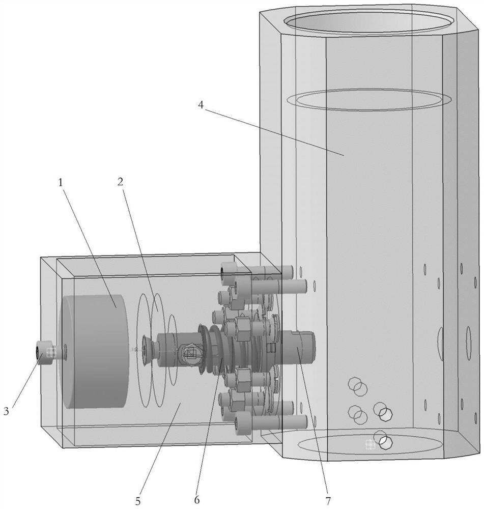
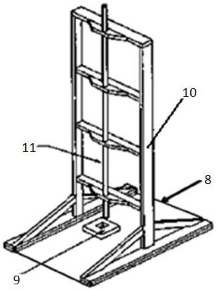
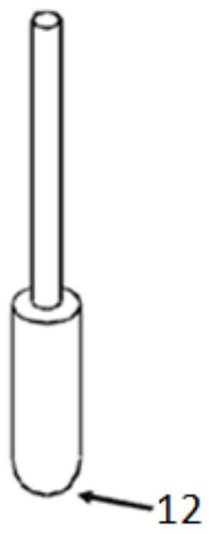
The invention belongs to the technical field of material and structure performance tests, and particularly relates to a secondary impact prevention device and method and a drop hammer impact test device with the secondary impact prevention device. The secondary impact prevention device comprises a guide pipe outlet section, a fixing box, an electromagnet suction cup, an impact head blocking block, an iron adsorption disc and a spring. A through hole is formed in the side wall of the outlet section of the guide pipe; one end of the fixing box is fixedly installed on the side wall of the guide pipe outlet section, and a sleeve matched with a through hole in the side wall of the guide pipe outlet section is arranged in the fixing box. The electromagnet suction cup is fixedly installed at the other end of the fixing box and provided with a power line outlet. The impact head blocking block is arranged in the sleeve, one end of the impact head blocking block can extend into the outlet section of the guide pipe through the through hole, and a limiting part is arranged on the impact head blocking block; the iron adsorption disc is fixedly mounted at the other end of the impact head blocking block; and the spring sleeves the impact head blocking block and is limited by the limiting part.

Description

technical field [0001] The application belongs to the testing technical field of material and structural performance testing, and in particular relates to a secondary impact prevention device and method and a drop weight impact test device having the same. Background technique [0002] Composite materials have poor resistance to low-velocity impact. The characteristic of impact damage resistance of composite materials is that in the absence of any symptoms on the impact surface, a wide range of internal delamination may occur inside, and its compressive bearing capacity will drop sharply. It is even less than 40% of the non-destructive structure, and endangers the safety of the aircraft structure. In view of this, the key to the damage tolerance requirements of composite structures is the consideration of impact damage. The introduction of impact damage mainly adopts the American ASTM D 7136 test standard "Standard Test Method for Measuring the Damage Resistance of Fiber Re...

Claims


Application Information

Patent Timeline
Patent Type & Authority Applications(China)
IPC IPC(8): G01M7/08
CPCG01M7/08
Inventor 熊华锋李磊李巍杨梦粤弓云昭
Owner CHINA AIRPLANT STRENGTH RES INST
Learn More