An electromagnetic deformable wing

An electromagnetic and elastic wing technology, applied in the field of elastic wings, can solve the problems of complex structure, large size and heavy weight of deformable elastic wings, and achieve the effect of light weight, large movable space and simple structure

Active Publication Date: 2022-05-17
BEIHANG UNIV
View PDF8 Cites 0 Cited by
  • Summary
  • Abstract
  • Description
  • Claims
  • Application Information

AI Technical Summary

Problems solved by technology

[0003] However, most of the existing deformable wings are mechanically deformed, and a large number of mechanical structures are arranged inside the deformable wings, which makes the deformable wings complex in structure, large in size and heavy in weight.

Method used


Image

  • An electromagnetic deformable wing
  • An electromagnetic deformable wing
  • An electromagnetic deformable wing

Examples


Embodiment 1

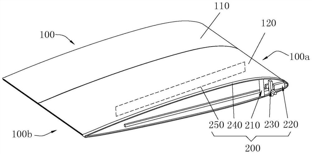
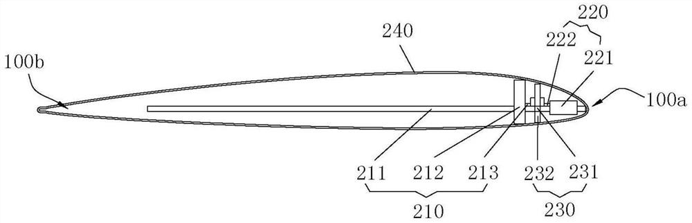
[0035] see Figure 1 to Figure 6 , this embodiment provides an electromagnetically deformable wing, which is applied to missiles.

[0036] see figure 1 and figure 2 , the electromagnetic deformable wing provided in this embodiment includes the wing body 100 and the deformation driving device 200 . Wherein, the end connecting the wing body 100 and the missile body is the wing root end, and the end away from the missile body is the wing tip end, and it is defined that the direction of the connecting line between the wing root end and the wing tip end is the extension direction of the wing body 100 . The wing body 100 also has a front edge portion 100a and a rear edge portion 100b along the width direction, the front edge portion 100a is thicker than the rear edge portion 100b, that is, the thickness from the front edge portion 100a to the rear edge portion 100b gradually becomes smaller, definition: front The direction of the line connecting the edge portion 100 a and the rear...


PUM


Abstract

The application provides an electromagnetically deformable wing, which relates to the technical field of wing. The electromagnetic deformable wing includes a wing body and a deformation driving device, the wing body includes a leading edge portion and a relative rear edge portion, and the deformation driving device includes a flexible conductor layer, a first driving component and an electromagnet; the electromagnet is arranged on the elastic body. In the wing body, the electromagnet is used to form a magnetic field along the lengthwise direction of the wing body; the flexible conductor layer is arranged around the wing body; the first drive assembly includes a first slide rail, a first slider and a first booster mechanism; A slider is slidably arranged on the first slide rail and forms a first circuit with the flexible conductor layer. The first booster mechanism is arranged on the first slide rail to give the first slider an initial velocity. The electromagnet is used to control the second A slider slides to the first preset position. Therefore, the structure of the electromagnetic control is simpler, the mechanical structure is reduced, the size is small, and the weight is light.

Description

technical field [0001] The invention relates to the technical field of elastic wings, in particular to an electromagnetically deformable elastic wing. Background technique [0002] Deformable wings are widely used in missiles. On the one hand, the deformation and folding of deformable wings save space for the transportation and mounting of missiles; on the other hand, the overall aerodynamic shape of missiles is changed through deformable wings, so that the Obtain better lift-to-drag ratio and aerodynamic characteristics at different flight speeds, enhance maneuverability, and improve combat capabilities. [0003] However, most of the existing deformable wings are mechanically deformed, and a large number of mechanical structures are arranged inside the deformable wings, which makes the deformable wings complex in structure, large in size and heavy in weight. Contents of the invention [0004] In order to overcome the deficiencies in the prior art, the present application...

Claims


Application Information

Patent Timeline
Patent Type & Authority Patents(China)
IPC IPC(8): F42B10/12
CPCF42B10/12Y02T50/10
Inventor 蔡国飙孙俊杰彭荀朱浩王鹏程李心曈
Owner BEIHANG UNIV
Why Eureka
Try Eureka