Low-temperature pipe body storage device

A storage device and low-temperature technology, which is applied in the field of freezing and cooling, can solve the problems of difficult consistency of test tube freezing rate, easy slipping of samples, poor temperature consistency, etc., and achieve the goal of improving the consistency of freezing rate, temperature consistency and working time Effect

Pending Publication Date: 2021-11-30
李志渊
View PDF7 Cites 0 Cited by
  • Summary
  • Abstract
  • Description
  • Claims
  • Application Information

AI Technical Summary

Problems solved by technology

The existing technology has the following technical problems: 1) In the case of wet ice contamination, the reagents are in direct contact with ice cubes and ice packs, or buried in ice piles; 2) The freezing rates of different test tubes are difficult to be consistent, and the temperature consistency is poor; 3 ) The sample is easy to slip and fall during transportation and taking, and the fixation is not firm; 4) Poor portability and short temperature control time; 5) The device is not easy to clean and disinfect

Method used


Image

  • Low-temperature pipe body storage device
  • Low-temperature pipe body storage device
  • Low-temperature pipe body storage device

Examples


Embodiment 1

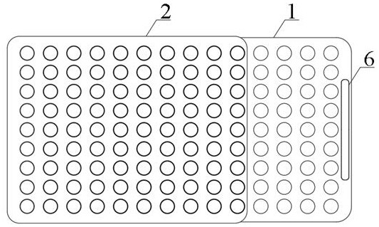
[0051] Such as Figure 1 to Figure 9 As shown, a low-temperature storage device with a tube body includes a heat-conducting metal block 1 and a sliding cover 2. In the figure, the heat-conducting metal block 1 is a metal shell structure, and the inside of the heat-conducting metal block 1 is sealed and filled with phase change materials. Generally, The heat-conducting metal block 1 is stored at -20°C. The slide cover 2 is slidably installed on the heat-conducting metal block 1. The distance between the lower surface of the slide cover 2 and the upper surface of the heat-conducting metal block 1 is 0.3cm to 1.5cm. The heat-conducting metal block 1 It is made of metal materials with good thermal conductivity such as aluminum alloy and copper, and the sliding cover 2 can be made of metal materials or non-metal materials.

[0052] Specifically, a plurality of working holes 101 for installing pipe fittings 3 are uniformly opened on the heat-conducting metal block 1. The pipe fittin...

Embodiment 2

[0056] Such as Figure 10 to Figure 13 , in order to prolong the low-temperature time of the heat-conducting metal block 1, the heat-conducting metal block 1 can be directly placed on the cold source, therefore, the metal cold block 4 is designed. The metal cold block 4 is a metal shell structure, and the inside of the heat-conducting metal block 1 is sealed and filled with phase change materials. The outer contour size of the metal cold block 4 is consistent with the outer contour size of the heat-conducting metal block 1. There is a side groove for installing the protection pad 401, and the thickness of the protection pad 401 is consistent with the depth of the side groove to ensure the smoothness of the surface of the metal cold block 4, and the two metal cold blocks 4 can fit closely and transfer heat. In this embodiment, the top of the heat-conducting metal block 1 can be provided with a concave platform for accommodating the protective pad 401 of the upper heat-conductin...

Embodiment 3

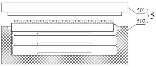
[0060] In this instance, figure 2 A heat-insulating box 5 is designed, which is composed of a box body 501 and a cover body 502. The heat-insulating box 5 is used to place the heat-conducting metal block 1, the sliding cover 2, the pipe fitting 3 and the metal cold block 4. Especially when long-distance transportation or storage is required, the use of the heat insulation box 5 can effectively reduce heat exchange and increase the low-temperature time. The heat insulation box 5 can be made of heat-insulating materials, such as high-density foam.


PUM


Abstract

The invention discloses a low-temperature pipe body storage device, belongs to the technical field of cooling and freezing, and particularly relates to the low-temperature pipe body storage device with temperature indicating and automatic fixing functions. The low-temperature pipe body storage device comprises a heat conduction metal block, a sliding cover, metal cold blocks, a heat insulation box, a temperature indicating device and the like; and the heat conduction metal block is a metal hollow shell structure, a plurality of working holes used for installing pipe fittings are evenly formed in the heat conduction metal block, the sliding cover is movably installed on the heat conduction metal block, pipe bodies can be reliably fixed through the repulsion effect of magnetic force, the pipe bodies are prevented from sliding off, the metal cold blocks make close contact through the magnetic force effect, and the temperature of the heat conduction metal block is visually managed through the temperature indicating device. Compared with an existing ice box, an existing low-temperature work station and an existing heat preservation box, the low-temperature pipe body storage device has a novel pipe body fixing mode and is convenient and reliable to use; in addition, the detachable metal cold blocks can greatly prolong the low-temperature time; and the technical problem that the working state of the traditional ice box is difficult to estimate can be solved by combining the temperature indicating device.

Description

technical field [0001] The invention belongs to the technical field of cooling and freezing, and in particular relates to a tube body cryogenic storage device. Background technique [0002] In the technical fields of biology, chemistry, and chemical engineering, some experiments need to be carried out in low temperature environments, and some samples also need to be transported in low temperature environments. Technicians generally use tools such as ice boxes, ice packs, and low temperature boxes to protect, transport, and store sensitive samples. The existing technology has the following technical problems: 1) In the case of wet ice contamination, the reagents are in direct contact with ice cubes and ice packs, or buried in ice piles; 2) The freezing rates of different test tubes are difficult to be consistent, and the temperature consistency is poor; 3 ) The sample is easy to slip and fall during transportation and taking, and the fixation is not firm; 4) The portability i...

Claims


Application Information

Patent Timeline
Patent Type & Authority Applications(China)
IPC IPC(8): F25D3/06F25D23/06F25D29/00
CPCF25D3/06F25D23/06F25D29/00
Inventor 李志渊
Owner 李志渊
Why Eureka
Try Eureka