Full-automatic surrounding type image support
A wrap-around, fully automatic technology, applied in the direction of machine/stand, supporting machine, optics, etc., can solve the problems of large limitations and difficult to meet the use of outdoor drama video recording
- Summary
- Abstract
- Description
- Claims
- Application Information
AI Technical Summary
Problems solved by technology
Method used
Image
Examples
Embodiment 1
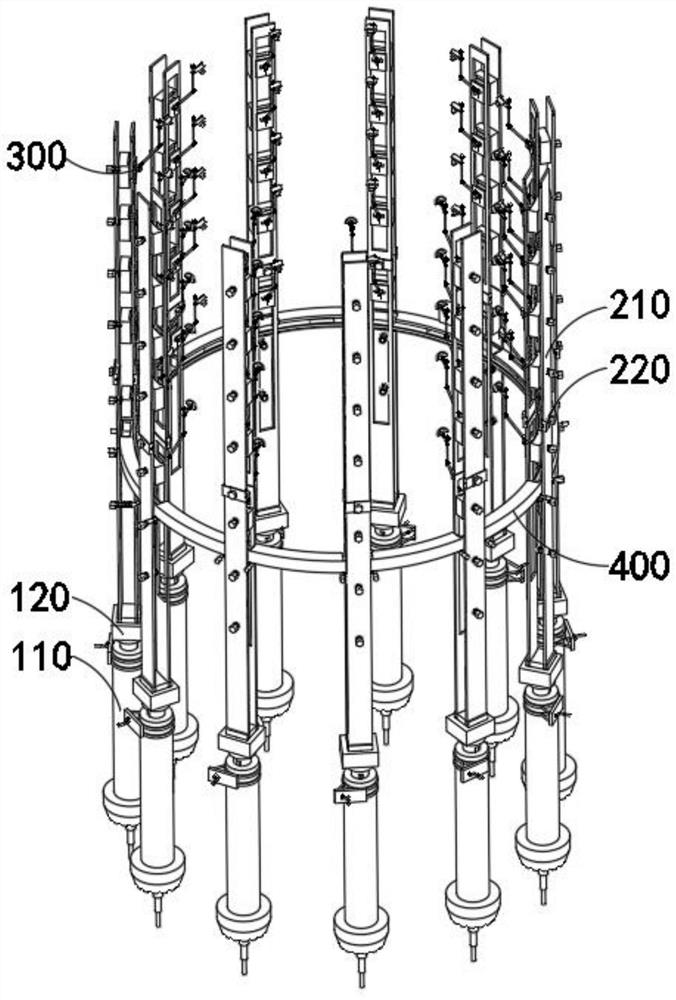
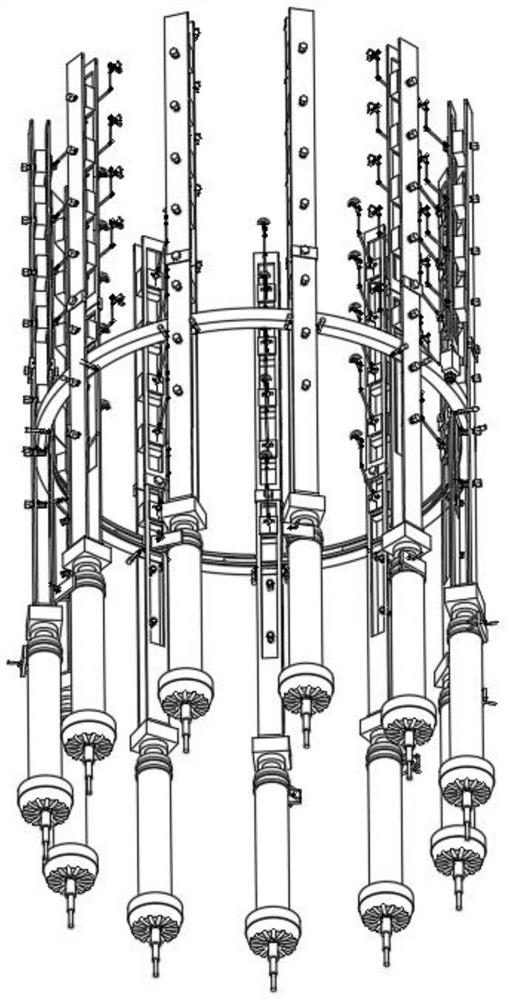
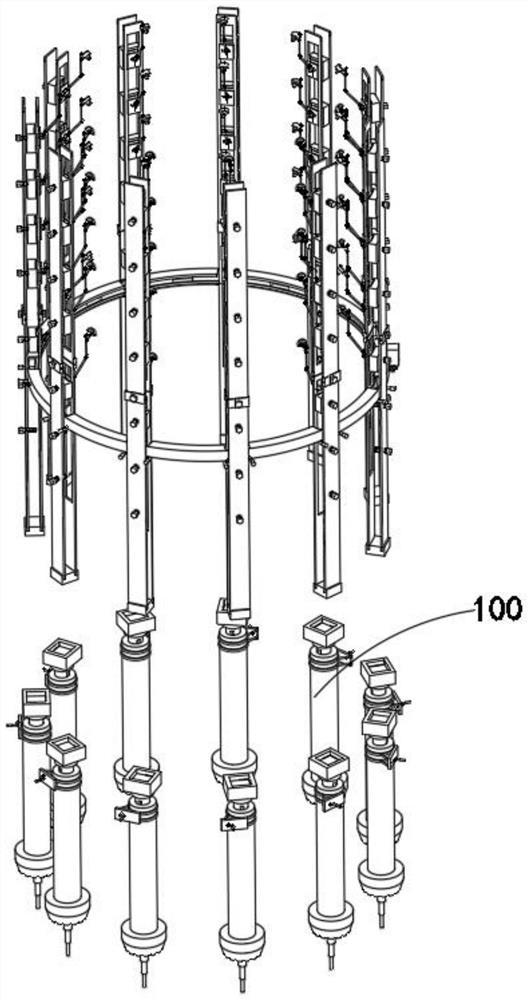
[0051] combine Figure 4-11 As shown, a fully automatic surround-type image support provided by the present invention includes a terrain adjustment mechanism 100, a lifting mechanism 200, a camera fixing mechanism 300 and a ring support mechanism 400, wherein the lifting mechanism 200 is installed on the terrain adjustment mechanism 100, and The camera fixing mechanism 300 is movably installed in the lifting mechanism 200 , and the ring support mechanism 400 is movably installed in the lifting mechanism 200 .
[0052] The terrain adjustment mechanism 100 includes an anti-sink combination 110 and a telescopic combination 120, and the anti-sink combination 110 also includes a main pile 111, a pressurized part 112, a protective casing 113, a central shaft 114 and a deflection rocker 115, and the telescopic combination 120 also includes a female Rod 121 and base 122, lifting mechanism 200 includes limit assembly 210 and engagement assembly 220, and limit assembly 210 also includes...
Embodiment 2
[0055] combine Figure 5 As shown, in the above embodiment, the protective shell 113 is fixedly installed outside the main pile 111, and the deflection rocker 115 and the central shaft rod 114 are movably installed in the protective shell 113. When the deflection rocker 115 rotates, the The eccentric rotation of the external tie rod will cause the central shaft 114 to move in a circle. At this time, the female rod 121 in the load-bearing state will not cause the central shaft 114 to reverse under load, and at the same time, the inner cavity of the rectangular stainless steel shell in the protective shell 113 is active. The central shaft 114 and the deflection rocker 115 are installed, and when the deflection rocker 115 rotates, the eccentric transmission of its external pull rod to the central shaft 114 can impel the gears in the central shaft 114 to control the fast lifting of the mother rod 121, and at the same time The effect of the pull rod can also avoid the problem that ...
Embodiment 3
[0057] combine Figure 8 As shown, in the above-mentioned embodiment, by setting the limit sub-frame 211 and the limit main frame 212 that can be increased, under the fixed connection between the limit limit sub-frame 211 and the plug-in 222, the device can realize the far and near view of the camera equipment. fast switching, after the two rectangular protrusions on the outer ends of the fastener 221 and the plug-in 222 are plugged into the grooves on the outside of the limiter sub-frame 211 and the limiter main frame 212, at this time, by turning the fixing nut in the fastener 221, the The stability between the limit sub-frame 211 and the limit main frame 212 can be quickly fixed, which facilitates the installation of the operator. The inside of the limit limit sub-frame 211 and the limit main frame 212 are opened with rectangular slots of different lengths. Since the limiting sub-frame 211 is the main load-bearing part, it is not appropriate to open the rectangular notch in...
PUM
 Abstract
Description
Claims
Application Information
 - R&D Engineer
- R&D Manager
- IP Professional
- Industry Leading Data Capabilities
- Powerful AI technology
- Patent DNA Extraction
Browse by: Latest US Patents, China's latest patents, Technical Efficacy Thesaurus, Application Domain, Technology Topic, Popular Technical Reports.
© 2024 PatSnap. All rights reserved.Legal|Privacy policy|Modern Slavery Act Transparency Statement|Sitemap|About US| Contact US: help@patsnap.com


