Composite floor slab construction method based on aluminum alloy formwork support

A technology of aluminum alloy formwork and laminated floor, which is applied in the direction of formwork/formwork/work frame, formwork/formwork/work frame connector, floor slab, etc. The problems of poor overturning ability, high labor and material costs, to achieve the effect of convenient dismantling and turnover, saving the number of supports, and reducing hoisting time

Pending Publication Date: 2021-11-30
CHINA HUASHI ENTERPRISES
View PDF0 Cites 0 Cited by
  • Summary
  • Abstract
  • Description
  • Claims
  • Application Information

AI Technical Summary

Problems solved by technology

At present, the traditional support system is usually used in the application and construction of laminated floor slabs. The traditional support system is composed of steel supports, U-shaped jacks, wooden I-beams and stable tripods. When applied, there are cumbersome installation processes and support point positioning. Difficult, difficult to monitor the elevation of the slab bottom, poor overall stability, inability to deal with joints between laminated slabs, high labor and material costs, especially during the hoisting of laminated slabs, the support system has poor anti-overturning ability and high safety hazards

Method used


Image

  • Composite floor slab construction method based on aluminum alloy formwork support
  • Composite floor slab construction method based on aluminum alloy formwork support
  • Composite floor slab construction method based on aluminum alloy formwork support

Examples


Embodiment Construction

[0037] In order to make the technical problems, technical solutions and beneficial effects to be solved by the present invention clearer, the present invention will be further described in detail below in conjunction with the accompanying drawings and embodiments. It should be understood that the specific embodiments described here are only used to explain the present invention, not to limit the present invention.

[0038] It should be noted that when a component is referred to as “fixing” or “setting” or “connecting” another component, it may be directly or indirectly located on the other component. The orientations or positions indicated by the terms "upper", "lower", "left", "right", "top", "bottom", "inner", "outer" etc. are based on the orientation or positions shown in the drawings and only It is for the convenience of description, and should not be understood as a limitation on the technical solution.

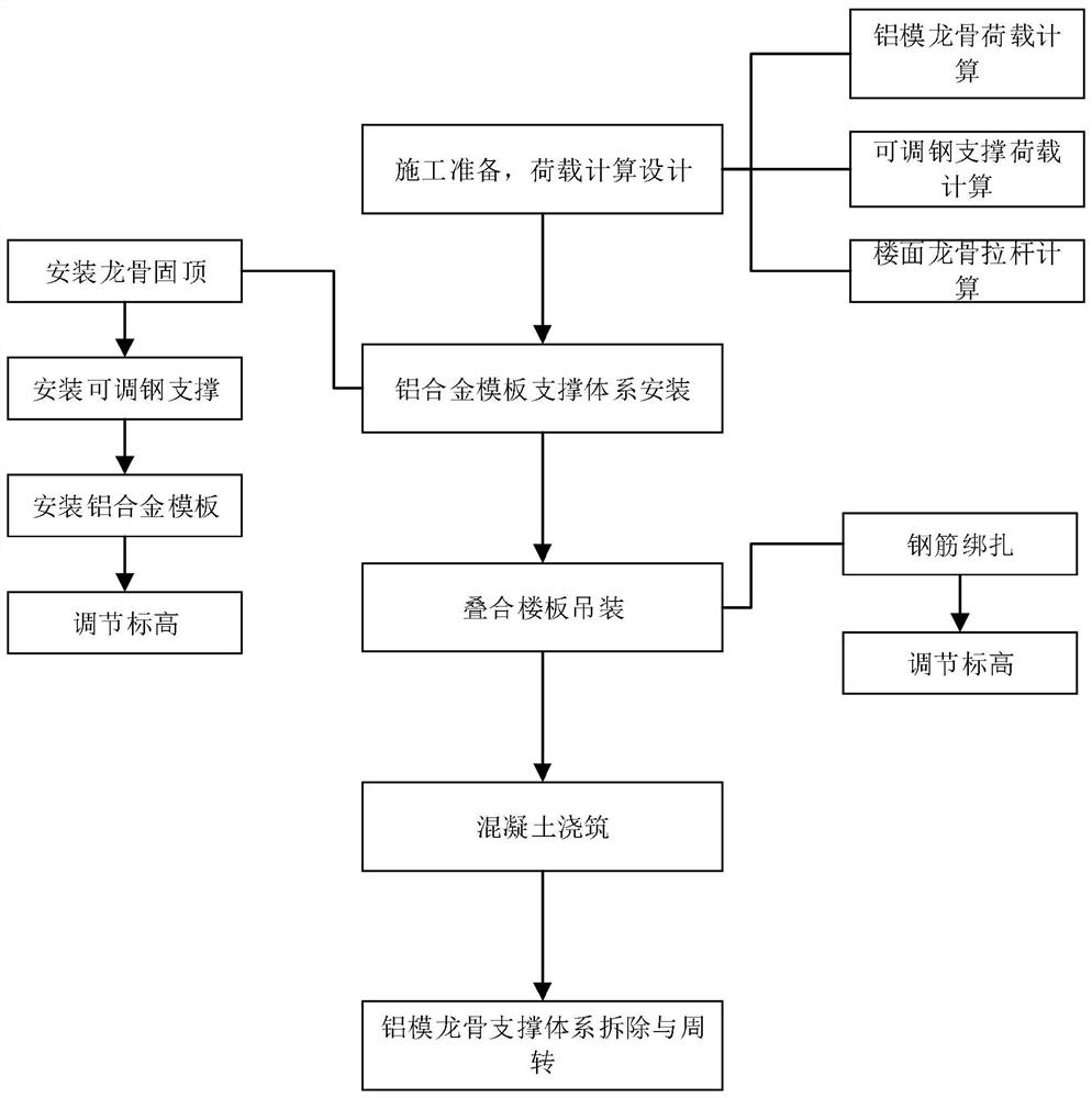
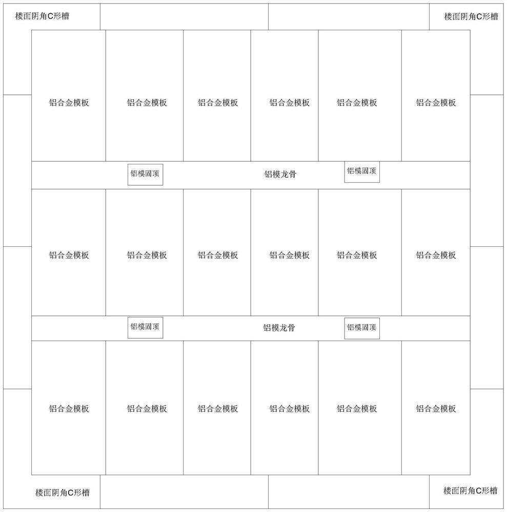
[0039] A construction method of laminated floor slabs supported by...


PUM


Abstract

The invention discloses a composite floor slab construction method based on aluminum alloy formwork support. The composite floor slab construction method comprises the following construction steps that S1, construction preparation is achieved: formwork matching design of an aluminum alloy formwork support system is completed; S2, the aluminum alloy formwork support system is installed; S3, composite floor slabs are hoisted, specifically, the composite floor slabs are arranged at the top of the aluminum alloy formwork support system in a hoisting mode and supported by aluminum alloy formworks and keel fixed tops, and the composite floor slabs are connected through reserved steel bars on the composite floor slabs bonded by steel bars; S4, concrete pouring is conducted, specifically, concrete is poured to the position above a composite floor slab; and S5, an aluminum formwork keel support system is dismantled and turned over, specifically, after concrete curing is achieved, an aluminum alloy formwork support system structure except aluminum formwork fixed tops is dismantled, and turning over is conducted. According to the composite floor slab construction method based on the aluminum alloy formwork support, the composite floor slab is supported through aluminum formwork keels and the aluminum formwork fixed tops, when a plurality of aluminum formwork fixed tops exist, all the aluminum formwork keels are connected through the aluminum alloy formworks, horizontal stability is guaranteed, and overturning is prevented in the hoisting process.

Description

technical field [0001] The invention relates to the technical field of engineering construction, and more specifically relates to a construction method of laminated floor slabs supported by aluminum alloy templates. Background technique [0002] The laminated floor slab is an assembled integral floor slab composed of prefabricated slabs and cast-in-place reinforced concrete layers. The laminated floor slab has good integrity, and the upper and lower surfaces of the slab are flat, which is convenient for decoration of the decorative layer. It has the advantages of convenient construction, good integrity, With the advantages of low energy consumption and low pollution, it is suitable for high-rise buildings and large-bay buildings that require high overall rigidity. It is widely used in prefabricated buildings because of its high on-site construction efficiency and good structural performance, and has become the current global construction industry. In today's trend, laminated...

Claims


Application Information

Patent Timeline
IPC IPC(8): E04G11/48E04G11/50E04G11/52E04G9/06E04G17/00E04B5/17
CPCE04G11/48E04G11/50E04G11/52E04G9/06E04G17/001E04B5/17
Inventor 刘杰廖军龙绍章黄军韩飞龙
Owner CHINA HUASHI ENTERPRISES
Why Eureka
Try Eureka