
Air supply system, control method for air supply system, and control program for air supply system

A technology of air supply and air drying, applied in the direction of separation methods, chemical instruments and methods, brakes, etc., can solve the problems of reduced purification function, achieve the effect of reducing consumption and maintaining dehumidification performance

Pending Publication Date: 2021-11-26
NABTESCO AUTOMOTIVE CORP
View PDF1 Cites 0 Cited by
  • Summary
  • Abstract
  • Description
  • Claims
  • Application Information

AI Technical Summary

Problems solved by technology

In addition, the purification function of the compressed air drying device decreases according to the supply amount of compressed dry air.

Method used


Image

  • Air supply system, control method for air supply system, and control program for air supply system
  • Air supply system, control method for air supply system, and control program for air supply system
  • Air supply system, control method for air supply system, and control program for air supply system

Examples


no. 1 approach

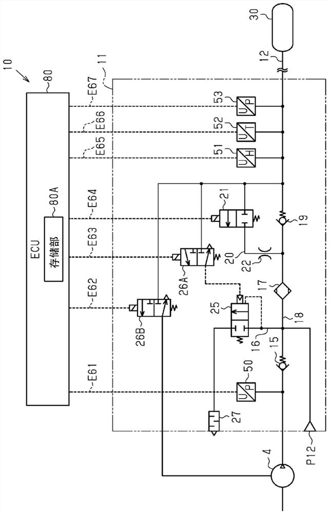
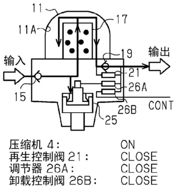
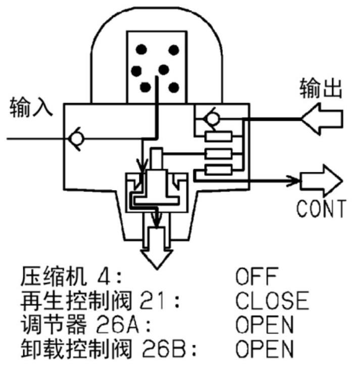
[0039] refer to Figure 1 to Figure 6 A first embodiment of the air supply system will be described. Air supply systems are installed in vehicles such as trucks, buses, and construction machinery. The compressed dry air generated by the air supply system is used, for example, in an air pressure system such as a brake system (brake device) or a suspension system (suspension device) of an automobile.

[0040]

[0041] refer to figure 1 The air supply system 10 will now be described. The air supply system 10 includes a compressor 4 , an air drying circuit 11 , and an ECU (Electronic Control Unit: Electronic Control Unit) 80 . In addition, the ECU 80 functions as a control device, a dehumidification operation execution unit, a regeneration operation execution unit, and a setting unit.

[0042] The ECU 80 is connected to the air drying circuit 11 via a plurality of wires E61 to E67. The ECU 80 includes a calculation unit, a communication interface unit, a volatile storage un...

no. 2 approach

[0122] Follow Figure 8 and Figure 9 , to describe the second embodiment. The second embodiment has the same point as the first embodiment in that the standard regeneration air volume and the corrected unit air volume are changed according to the state of the air drying circuit 11 to calculate the regeneration air volume. In addition, in the first embodiment, the standard regeneration air volume and the corrected unit air volume are changed according to the cut-out pressure, but in the second embodiment, the standard regeneration air volume and the corrected unit air volume are changed according to the temperature of the compressed dry air , which is different from the first embodiment in this point. Therefore, in the following, configurations different from those of the first embodiment will be mainly described in detail, and detailed descriptions of the same configurations will be omitted for convenience of description.

[0123] Figure 8A It is a map 110 for setting the ...


PUM


Abstract

The present invention decreases the consumption of compressed dry air while maintaining excellent dehumidification performance. This air supply system (10) comprises: an air drying circuit (11) that is provided between a compressor (4) for sending compressed air and an air tank (30) for storing compressed dry air, and that comprises a filter (17) for capturing moisture; and an ECU (80) that controls the air drying circuit (11). The ECU (80): performs a dehumidification operation in which the air drying circuit (11) is controlled and the compressed air sent from the compressor (4) is passed through the filter (17) in the forward direction and supplied to the air tank (30); performs a regeneration operation in which the air drying circuit (11) is controlled and the compressed dry air stored in the air tank (30) is passed through the filter (17) in the reverse direction and the fluid that passes through the filter is discharged from a drain discharge port (27); and sets the amount of regeneration air consumed in the regeneration operation in response to the operating state of the compressor (4).

Description

technical field [0001] The present disclosure relates to an air supply system, a control method of the air supply system, and a control program of the air supply system. Background technique [0002] In vehicles such as trucks, buses, and construction machinery, compressed air delivered from a compressor is used to control air pressure systems including brake systems and suspension systems. This compressed air contains liquid impurities such as moisture contained in the atmosphere and oil for lubricating the interior of the compressor. If compressed air containing a large amount of water and oil enters the air pressure system, it may cause rust and swelling of rubber components, which may cause malfunctions. Therefore, a compressed air drying device for removing impurities such as moisture and oil in the compressed air is installed downstream of the compressor. [0003] Compressed air drying units are equipped with various valves and filters containing desiccant. The comp...

Claims


Application Information

Patent Timeline
Patent Type & Authority Applications(China)
IPC IPC(8): B60T17/00B01D53/26F04B41/02
CPCF04B41/02B60T17/00B01D53/26
Inventor 杉尾卓也除田和也
Owner NABTESCO AUTOMOTIVE CORP
Learn More