Shaping equipment for wiring harness connectors

A wire harness and equipment technology, applied in the field of shaping equipment for wire harness joints, can solve problems such as high labor intensity, low production efficiency, and difficulty in ensuring quality stability, and achieve the effect of improving processing efficiency

Active Publication Date: 2021-11-26
WUHU BOKANG ELECTRICAL
View PDF3 Cites 0 Cited by
  • Summary
  • Abstract
  • Description
  • Claims
  • Application Information

AI Technical Summary

Problems solved by technology

[0002] In the traditional wire harness processing process, it is necessary to peel the wires and then pass through the squarer and weld them into one strand. In the existing squarer technology, a single joint is usually sent into the squarer by manual means. Square processing, especially for the wiring harness of multi-strand copper wire joints, generally two strands, before sending them into the square machine, the two strands of copper wire joints need to be manually smoothed, that is, separated by a certain distance and angle before they can be processed. Carrying out a single pressing process is labor-intensive, low in production efficiency, and difficult to guarantee quality stability

Method used


Image

  • Shaping equipment for wiring harness connectors
  • Shaping equipment for wiring harness connectors
  • Shaping equipment for wiring harness connectors

Examples


Embodiment Construction

[0029] In order to make the technical means, creative features, goals and effects achieved by the present invention easy to understand, the present invention will be further described below in conjunction with specific embodiments.

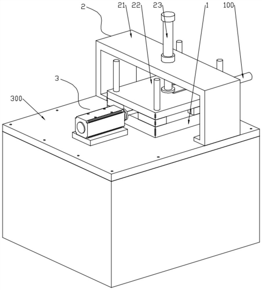
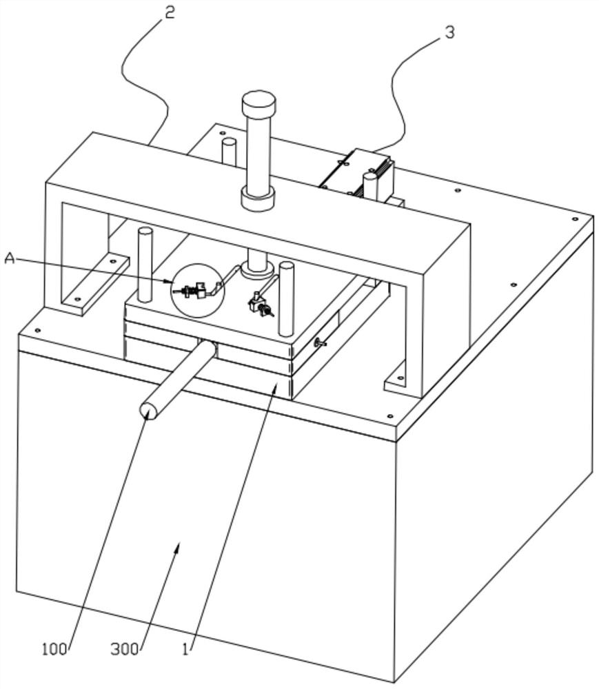
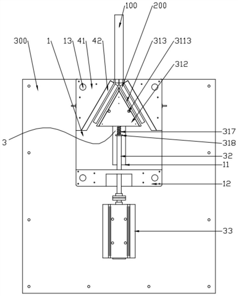
[0030] Such as Figure 1 to Figure 8 As shown, a shaping device for wire harness joints includes a base 1, a press-down assembly 2, a stamping assembly 3 and a side mold assembly 4. Four guide posts 13 are installed on the base 1, and the press-down assembly 2 The pressing plate 22 is slidably connected to the guide column 13. The pressing assembly 2 is used to limit the wire harness placed on the base 1 in the vertical direction. Part 4 cooperates to realize simultaneous crimping of two wire harness connectors. Two symmetrically arranged side mold assemblies 4 are installed on the base 1 to form a "V"-shaped stamping cavity. The positive conductive plate in the stamping assembly 3 313 can cooperate with the positive conductive component 5 connec...


PUM


Abstract

The invention discloses shaping equipment for wire harness connectors, and relates to the technical field of automobile wire harness machining. The shaping equipment comprises a base, a downward pressing assembly, a stamping assembly and a side die assembly, the downward pressing assembly is used for limiting a wire harness placed on the base in the vertical direction, the stamping assembly is horizontally installed on the base and matched with the side die assembly to achieve squaring treatment on two wire harness connectors at the same time, a positive electrode conductive plate in the stamping assembly can be matched with a positive electrode conductive assembly, connected to the positive electrode of a power source, on the pressing plate, and a negative electrode conductive plate in the side die assembly is connected to the negative electrode of the power source. In a squaring process, by means of the positive electrode conductive plate and the negative electrode conductive plate, welding treatment of the wire hardness connectors is achieved; by means of a pressing mechanism and the matched side die assembly, squaring treatment of the two copper wire connectors can be achieved at a time, and compared with a traditional single copper wire squaring process and a wire stroking process before squaring, the machining efficiency is remarkably improved.

Description

technical field [0001] The invention belongs to the technical field of automobile wire harness processing, and in particular relates to a shaping device for wire harness joints. Background technique [0002] In the traditional wire harness processing process, it is necessary to peel the wires and then pass through the squarer and weld them into one strand. In the existing squarer technology, a single joint is usually sent into the squarer by manual means. Square processing, especially for the wiring harness of multi-strand copper wire joints, generally two strands, before sending them into the square machine, the two strands of copper wire joints need to be manually smoothed, that is, separated by a certain distance and angle before they can be processed. Carrying out the processing of single pressing square, labor intensity is big, production efficiency is low, and quality stability is difficult to guarantee. Contents of the invention [0003] The object of the present i...

Claims


Application Information

Patent Timeline
Patent Type & Authority Applications(China)
IPC IPC(8): H01R43/05
CPCH01R43/05
Inventor 方良闵珞琪许斌李国英
Owner WUHU BOKANG ELECTRICAL
Why Eureka
Try Eureka