
Ocean wind power generation single pile foundation scouring protection device

A single-pile foundation and protection device technology is applied in the field of offshore wind power to achieve the effects of strengthening the blocking effect, saving costs, and increasing the production of aquaculture

Pending Publication Date: 2021-11-26
ZHOUSHAN OCEAN UNIV SCI & TECH RES INST CO LTD
View PDF7 Cites 6 Cited by
  • Summary
  • Abstract
  • Description
  • Claims
  • Application Information

AI Technical Summary

Problems solved by technology

Although the above-mentioned technical solution can protect the single pile foundation of marine wind power generation from scour to a certain extent, it requires regular post-maintenance, such as the stones being transported by hydraulic power, and divers are required to enter the water and manually move the stones back. Go to the designated anti-scouring location and refurbish

Method used


Image

  • Ocean wind power generation single pile foundation scouring protection device
  • Ocean wind power generation single pile foundation scouring protection device
  • Ocean wind power generation single pile foundation scouring protection device

Examples


Embodiment 1

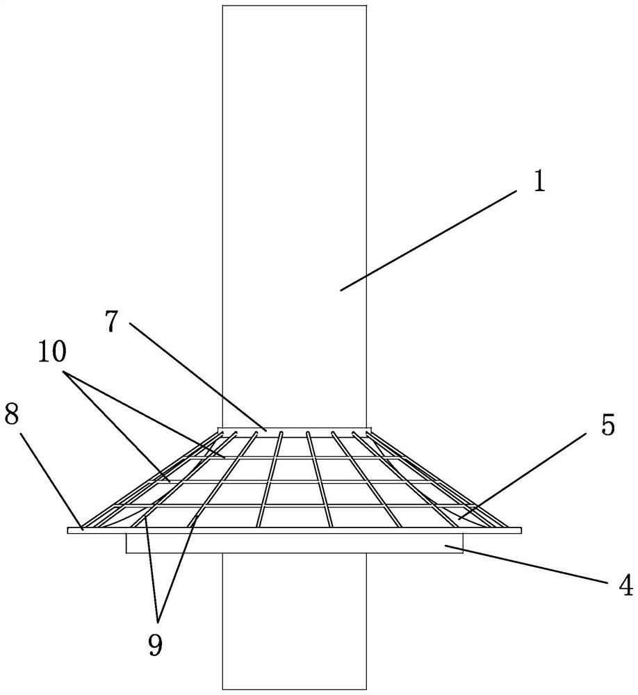
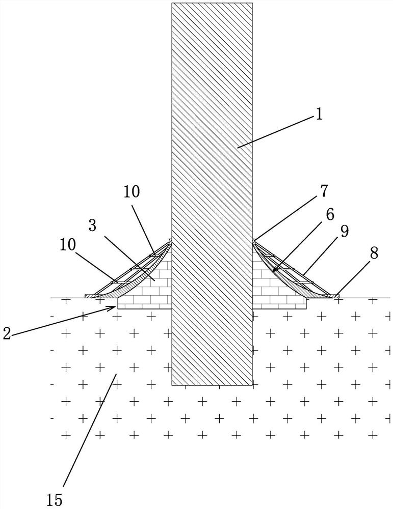
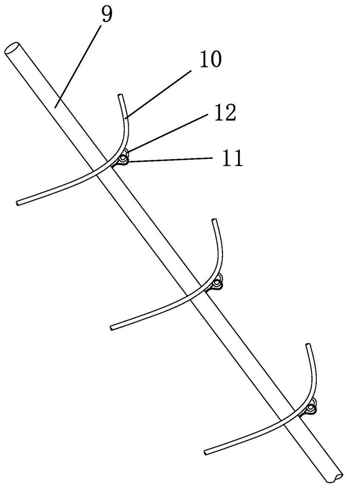
[0021] Such as Figure 1-Figure 3 As shown, the marine wind power monopile foundation erosion protection device includes a backfill gravel layer 2 surrounding the periphery of the monopile foundation 1. The backfill gravel layer 2 includes a conical rockfill layer 3 above the surface of the seabed 15 and a The soil-burrowed rock-fill layer 4 below the surface of the seabed 15, and the surface of the cone-shaped rock-fill layer 3 are covered with a buffer layer 5.

[0022] The buffer layer 5 is filled and cemented on the outer periphery of the conical rockfill layer 3 by means of grouting with cementitious materials. Using the grouting method, the buffer layer 5 has good integrity and is not easily damaged. A certain pressure, such as 0.5-1.5 MPa, is properly applied during the grouting process to improve the grouting effect and make the cemented buffer layer 5 more compact and durable. The cementitious material is a hydraulic cementitious material, including Portland cement, ...

Embodiment 2

[0028] Such as Figure 4 As shown, another marine rescue system based on the Internet of Things provided by the second embodiment of the present invention, the system is improved on the basis of the system structure of the first embodiment above: the lower support ring 8 is also provided with a breeding system surrounding the buffer layer 5 The net cage 13 constitutes a culture space 14 for cultivating fry between the culture net cage 13 and the culture rope 10 . In this way, the polyculture of marine economic crops and fish can not only reduce feed feeding, but also nourish marine economic crops with fish feces, which is conducive to the long-term stable operation of marine ranches and compensates for the impact on the sea area environment during the construction of wind farms. and resource damage.

[0029] The principle of use of the present invention is as follows: the marine economic crops on the breeding net build the first line of anti-scouring defense. When the ocean c...


PUM


Abstract

The invention provides an ocean wind power generation single pile foundation scouring protection device, and belongs to the technical field of ocean wind power. The ocean wind power generation single pile foundation scouring protection device comprises a backfill gravel layer arranged on the periphery of the single pile foundation in a surrounding mode, the backfill gravel layer comprises a conical rock-fill layer located above the surface of a seabed and a soil-entering rock-fill layer located below the surface of the seabed, and the surface of the conical rock-fill layer is wrapped with a buffer layer. The ocean wind power generation single pile foundation scouring protection device is good in protection effect and stable and durable in structure, meanwhile, the ocean pasture technology is combined, the breeding output is improved, the economic benefits are improved, the sea is intensively used, the resource utilization efficiency is improved, and therefore the construction cost and the operation and maintenance cost are reduced.

Description

technical field [0001] The invention belongs to the technical field of marine wind power, and in particular relates to a single pile foundation scour protection device for marine wind power generation. Background technique [0002] In the field of offshore wind power engineering technology, large-diameter monopile foundations are widely used in offshore wind power projects because of their simple structure, convenient fabrication, and high construction efficiency. During the operation of the single pile foundation, it needs to withstand environmental factors such as waves and currents. When the ocean current flows through the single pile foundation, a vortex structure will be formed around the single pile foundation, and the vortex will take away the seabed soil around the single pile foundation, and then form a scour pit around the single pile foundation. The existence of the scour pit will directly affect the bearing capacity of the single pile foundation. If the scour pi...

Claims


Application Information

Patent Timeline
Patent Type & Authority Applications(China)
IPC IPC(8): E02D31/06E02D27/16E02D27/42E02D27/52E02D5/60F03D13/25A01G33/00A01K61/60A01K61/65
CPCE02D31/06E02D27/16E02D27/425E02D27/525E02D5/60F03D13/22F03D13/25A01G33/00A01K61/60A01K61/65Y02E10/72Y02E10/727Y02E10/728Y02A40/81Y02P60/60
Inventor 张华王晨张聪徐从晓
Owner ZHOUSHAN OCEAN UNIV SCI & TECH RES INST CO LTD
Learn More