Coded disc mounting and positioning device of photoelectric non-contact ship shaft power meter

A photoelectric code disc, installation and positioning technology, applied to workpiece clamping devices, manufacturing tools, etc., can solve problems such as eccentricity errors, measurement result errors, and non-perpendicular axes, so as to improve measurement accuracy, eliminate eccentricity errors, and solve installation errors. Effect

Active Publication Date: 2021-11-26
WUHAN UNIV OF TECH
View PDF7 Cites 0 Cited by
  • Summary
  • Abstract
  • Description
  • Claims
  • Application Information

AI Technical Summary

Problems solved by technology

The installation state of the photoelectric code disc on the measured rotating shaft will mainly cause two kinds of errors: one is the eccentricity error caused by the misalignment of the center of the photoelectric code disc and the axis of the measured rotating shaft; the other is the plane where the photoelectric code disc is located. Tilt error that is not perpendicular to the axis of the measured rotating shaft
During the installation process of the shaft power meter, the photoelectric code disk needs to be placed in the U-shaped groove of the photoelectric sensor, that is, between the laser emitting end and the laser receiving end. If the plane of the photoelectric code disk is not parallel to the inner surface of the U-shaped groove of the photoelectric sensor , will also cause a large error impact on the subsequent measurement results

Method used


Image

  • Coded disc mounting and positioning device of photoelectric non-contact ship shaft power meter
  • Coded disc mounting and positioning device of photoelectric non-contact ship shaft power meter
  • Coded disc mounting and positioning device of photoelectric non-contact ship shaft power meter

Examples


Embodiment Construction

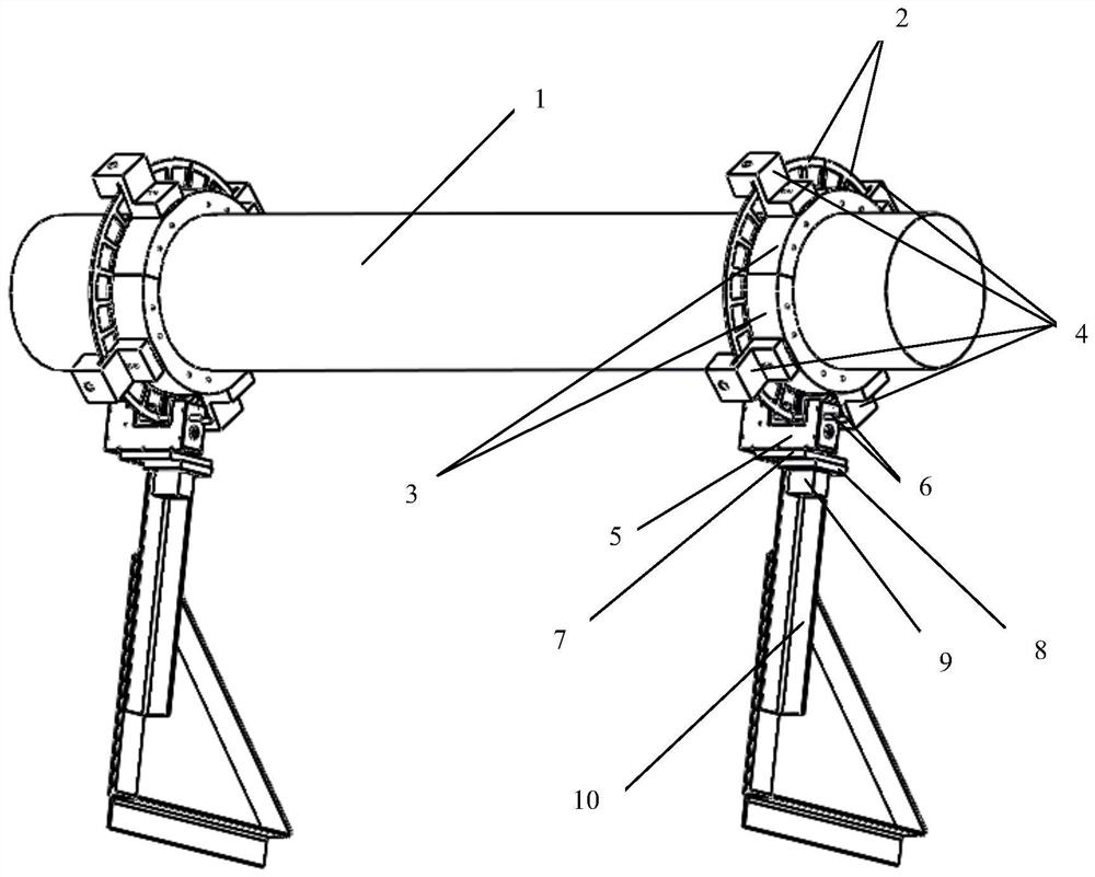
[0027] The technical solutions of the present invention will be described below in conjunction with the accompanying drawings and embodiments.

[0028] Such as Figure 1 to Figure 5 As shown, the code disc installation and positioning device of a photoelectric non-contact ship shaft power meter according to the present invention includes a measured rotating shaft 1, and the two ends of the shaft body of the measured rotating shaft 1 are respectively equipped with photoelectric codes through fixed installation accessories. Disk assembly 2, the plane of the photoelectric code disk assembly 2 is set perpendicular to the axis of the measured rotating shaft 1, and the center of the photoelectric code disk assembly 2 is set coaxially with the axis of the measured rotating shaft 1, and the photoelectric code disk assembly 2 passes through The fixed component is fixed with a photoelectric sensor 5, and the photoelectric sensor 5 is connected to the fixed base or the fixed platform col...


PUM


Abstract

The invention relates to the technical field of mounting and positioning devices, in particular to a coded disc mounting and positioning device of a photoelectric non-contact ship shaft power meter. The device comprises a to-be-detected rotating shaft, photoelectric coded disc assemblies are respectively mounted at two ends of a shaft body of the to-be-detected rotating shaft through fixing and mounting accessories, a plane of each photoelectric coded disc assembly is perpendicular to an axis of the to-be-detected rotating shaft, circle centers of the photoelectric coded disc assemblies and the axis of the to-be-detected rotating shaft are coaxially arranged, photoelectric sensors are fixed to the photoelectric coded disc assemblies through fixing assemblies, and the photoelectric sensors are connected to fixed bases or fixed stands on a ship through connecting assemblies. According to the device, an eccentric error caused by the fact that the circle centers of the photoelectric coded disc assemblies do not coincide with the axis of the to-be-detected rotating shaft is eliminated, the problem of an offset error of tiny inclination of the photoelectric coded disc assemblies on the to-be-detected rotating shaft due to overlarge torque in a high-speed rotating process of the to-be-detected rotating shaft is avoided, therefore, the installation error problem of the whole shaft power meter is solved, and the measurement precision of the shaft power is improved.

Description

technical field [0001] The invention relates to the technical field of installation and positioning devices, in particular to a code disc installation and positioning device for a photoelectric non-contact ship shaft power meter. Background technique [0002] In the ship power system, shaft power is one of the main performance parameters for testing the system, and it can also be used as an information source for fault alarms. Measuring the shaft power through the ship shaft power meter can realize the real-time monitoring of the operating status of the main engine of the ship. By analyzing the test data, the cause of the failure can be quickly and accurately found, so as to realize the diagnosis of the system failure. At present, based on the research and development status of shaft power meters at home and abroad, the problem of affecting the measured data due to the installation error of the device itself has been paid more and more attention. The installation state of t...

Claims


Application Information

Patent Timeline
IPC IPC(8): B25B11/00
CPCB25B11/00
Inventor 杨琨刘栩岩王恒谢一丁张涛
Owner WUHAN UNIV OF TECH
Why Eureka
Try Eureka