Extrusion and crushing rod for auxiliary feeding device

A technology of extrusion crushing and shearing, which is applied in the direction of therapeutic feeding tubes and grain processing, etc. It can solve the problems that the crushing degree only reaches granulation, does not have food crushing ability, and has a single function, and achieves low wear and calorific value, Effect of increasing transmission volume and improving transmission efficiency

Pending Publication Date: 2021-11-26
JIANGSU UNIV OF SCI & TECH IND TECH RES INST OF ZHANGJIAGANG
View PDF8 Cites 0 Cited by
  • Summary
  • Abstract
  • Description
  • Claims
  • Application Information

AI Technical Summary

Problems solved by technology

Although these three types of rods are simple in structure, flexible in design, low in cost, and high in extrusion transmission efficiency, they have single functions and can only complete one-way transmission of food.
In some occasions where food needs to be crushed, due to the limitation of the existing extrusion rod structure, it generally does not have the ability to crush food, so that in this case, the existing auxiliary feeding device is less practical
[0005] At present, in the market, there are not many occasions where the rod and the crushing structure are connected together. Many crushing structures are in the form of blades, but in terms of food crushing occasions, the degree of crushing of the blades only reaches granulation. In the case of a degree of crushing and muddying, a new crushing structure is required for high crushing

Method used


Image

  • Extrusion and crushing rod for auxiliary feeding device
  • Extrusion and crushing rod for auxiliary feeding device
  • Extrusion and crushing rod for auxiliary feeding device

Examples


Embodiment Construction

[0025] The specific implementation manner of the present invention will be described in more detail below with reference to schematic diagrams. The advantages and features of the present invention will be more apparent from the following description. It should be noted that all the drawings are in a very simplified form and use imprecise scales, and are only used to facilitate and clearly assist the purpose of illustrating the embodiments of the present invention.

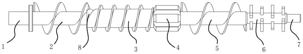
[0026] like Figure 1-Figure 3 As shown, a crushing rod for an auxiliary feeding device provided by an embodiment of the present invention is rotatably installed in a communication hole on the feeding assisting device, and the length-to-diameter ratio of the crushing rod is 22:1. The crushing rod is divided into connecting section 1, first conveying section 2, first shearing section 3, second shearing section 4, second conveying section 5, solid-liquid mixing section 6 and supporting section in the axial direction...


PUM


Abstract

The invention provides an extrusion and crushing rod for an auxiliary feeding device, the extrusion and crushing rod is rotatably mounted in a communicating hole in the auxiliary feeding device, and the extrusion and crushing rod is sequentially divided into a connecting section, a first conveying section, a first shearing section, a second shearing section, a second conveying section, a solid-liquid mixing section and a supporting section in the axial direction, wherein the first conveying section and the second conveying section are the same in structure and are both single-spiral worm structures; the first shearing section is also of a single spiral worm structure, the lead of the first shearing section is smaller than that of the first conveying section, and the screw flight height of the first shearing section is smaller than that of the first conveying section; the second shearing section is a cylindrical body formed after a plurality of longitudinal grooves penetrating in the axial direction are formed in the circumferential surface of the cylinder at equal intervals, and the shaft diameter of the second shearing section is consistent with the inner diameter of the communicating hole; and the solid-liquid mixing section is provided with a plurality of rectangular teeth distributed at intervals in the axial direction. By designing the structure and the layout mode of the extrusion and crushing rod, the crushing effect is enhanced, the extrusion efficiency is improved, and the waste phenomenon is reduced.

Description

technical field [0001] The invention relates to the technical field of feeding equipment for the elderly, in particular to a crushing rod for an auxiliary feeding device. Background technique [0002] With the aggravation of the population aging problem, people pay more and more attention to the home care and diet of the elderly. Many elderly people can only eat some liquid food due to aging teeth or other physical reasons. Due to the inherent fluidity of liquid food, for some elderly people whose hands are prone to shaking, it is difficult to use traditional tableware to eat by themselves. If other people assist in feeding, it is easy to increase the risk of choking for the elderly. [0003] At present, it is a feasible solution to use assisted feeding devices to assist the elderly to eat independently. The auxiliary eating device drives the extruding rod to rotate through the motor, thereby extruding the food for assisting eating. [0004] Extrusion rods can be divided i...

Claims


Application Information

Patent Timeline
Patent Type & Authority Applications(China)
IPC IPC(8): A61J15/00B02C18/14
CPCA61J15/0026B02C18/141
Inventor 桂春喜张均华方海峰董硕曹晋黄帅博刘天鹏陶丽佳王振丁亮
Owner JIANGSU UNIV OF SCI & TECH IND TECH RES INST OF ZHANGJIAGANG
Why Eureka
Try Eureka