Autonomous ventilation and heat exchange type power distribution cabinet

A technology for power distribution cabinets and ventilation hoods, which is applied in the substation/power distribution device shell, substation/switchgear cooling/ventilation, electrical components, etc. Issues such as the safe use of components to achieve the effect of improving ventilation and heat dissipation

Active Publication Date: 2021-11-23
江苏大师兄电气设备有限公司
View PDF5 Cites 5 Cited by
  • Summary
  • Abstract
  • Description
  • Claims
  • Application Information

AI Technical Summary

Problems solved by technology

Because there are many electrical components inside the power distribution cabinet, it will generate a lot of heat when it is working. When the heat accumulates too much, it is not conducive to the normal operation of the power distribution cabinet.
[0003] In the prior art, in order to prevent a large amount of heat stored in the cabinet from dissipating, a cooling fan is generally installed at the vent on the end wall of the cabinet to dissipate heat. Although it plays the role of air flow, it is difficult to remove the dust in the outside air. Interception, and in low temperature environment, due to the vents make the inside of the cabinet and the outside still maintain a certain air circulation effect, so in the case of long-term use, there will still be a lot of dust inside the cabinet, and at the same time, the water vapor from the outside will also enter the cabinet , is not conducive to the safe use of electrical components

Method used


Image

  • Autonomous ventilation and heat exchange type power distribution cabinet
  • Autonomous ventilation and heat exchange type power distribution cabinet
  • Autonomous ventilation and heat exchange type power distribution cabinet

Examples


Embodiment 1

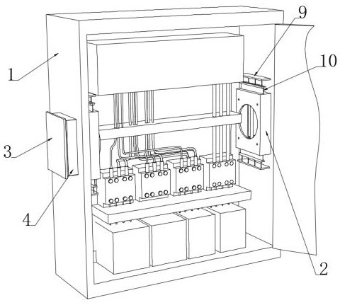
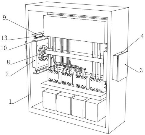
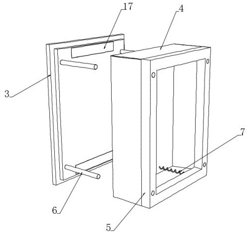
[0045] see Figure 1-4 , a self-ventilating and heat-exchanging power distribution cabinet, including a cabinet body 1, vents are opened on the left and right end walls of the cabinet body 1, and inner ventilation hoods 2 located inside the vents are provided on the opposite inner walls of the cabinet body 1 , the inner side walls of a pair of air vents are all connected with a positioning frame 5, and the outer ends of a pair of positioning frames 5 are provided with an outer dust-proof plate 3, and an elastic dust-proof cloth 4 is passed between the outer dust-proof plate 3 and the positioning frame 5 Convergence, the upper and lower outer end walls of the positioning frame 5 are also fixedly connected with a pair of tension springs 7 connected with the inner walls of the upper and lower ends of the outer dustproof plate 3, and the end walls of the positioning frame 5 are provided with embedded holes for tension spring 7 fixing. Holes, a pair of inner ventilation hoods 2 are...


PUM


Abstract

The invention discloses an autonomous ventilation and heat exchange type power distribution cabinet, which belongs to the technical field of power distribution cabinets. Inner ventilation hoods and outer dustproof plates are additionally arranged at left and right ventilation openings of a cabinet body, when the cabinet body is in a normal low-temperature environment, a pair of outer dustproof plates are connected to the ventilation openings in a sealed manner, so that the dustproof and moisture-proof effects are achieved, and when the interior of the cabinet body is in a high-temperature environment, a plurality of memory deformation rods connected to a flexible magnetic isolation sheet recover to a spring phase state due to high temperature and pull the flexible magnetic isolation sheet to turn outwards, after an inner magnetic sheet is slowly exposed, the inner magnetic sheet plays a magnetic repulsive role on an outer magnetic sheet, so that an outer dustproof plate moves outwards, and after the outer dustproof plate is separated from a ventilation opening, the elastic dustproof cloth connected between the outer dustproof plate and the positioning frame is exposed, at the moment, air outside the cabinet is guided into the cabinet body through the elastic dustproof cloth, autonomous ventilation and heat exchange are achieved according to the environment in the cabinet, and meanwhile the ventilation and heat dissipation effects are further improved by means of starting of the heat dissipation fan.

Description

technical field [0001] The invention relates to the technical field of power distribution cabinets, and more specifically relates to a self-ventilating and heat-exchanging power distribution cabinet. Background technique [0002] The power distribution cabinet is the final equipment of the power distribution system. The power distribution cabinet is used in the occasions where the load is relatively scattered and the circuit is small. It distributes the electric energy of a certain circuit of the upper-level power distribution equipment to the nearest load. Because there are many electrical components inside the power distribution cabinet, it will generate a lot of heat when it is working. When the heat accumulates too much, it is not conducive to the normal operation of the power distribution cabinet. [0003] In the prior art, in order to prevent a large amount of heat stored in the cabinet from dissipating, a cooling fan is generally installed at the vent on the end wall...

Claims


Application Information

Patent Timeline
Patent Type & Authority Applications(China)
IPC IPC(8): H02B1/56H02B1/28B01D46/02H02B1/32
CPCH02B1/565H02B1/28B01D46/02B01D46/0004H02B1/32
Inventor 郭闵武
Owner 江苏大师兄电气设备有限公司
Why Eureka
Try Eureka