
Optical fiber helical antenna wave field converter

A helical antenna and converter technology, which is applied in the field of optical fiber helical antenna wave field converters, can solve problems such as inability to realize light field conversion, and achieve the effect of breaking through the diffraction limit

Pending Publication Date: 2021-11-23
GUILIN UNIV OF ELECTRONIC TECH
View PDF2 Cites 0 Cited by
  • Summary
  • Abstract
  • Description
  • Claims
  • Application Information

AI Technical Summary

Problems solved by technology

The devices based on the combination of optical fiber and antenna proposed in the above patents are mostly used in optical communication, and cannot realize light field conversion, especially the conversion of the longitudinal and transverse polarization components of the light field.

Method used


Image

  • Optical fiber helical antenna wave field converter
  • Optical fiber helical antenna wave field converter
  • Optical fiber helical antenna wave field converter

Examples


Embodiment Construction

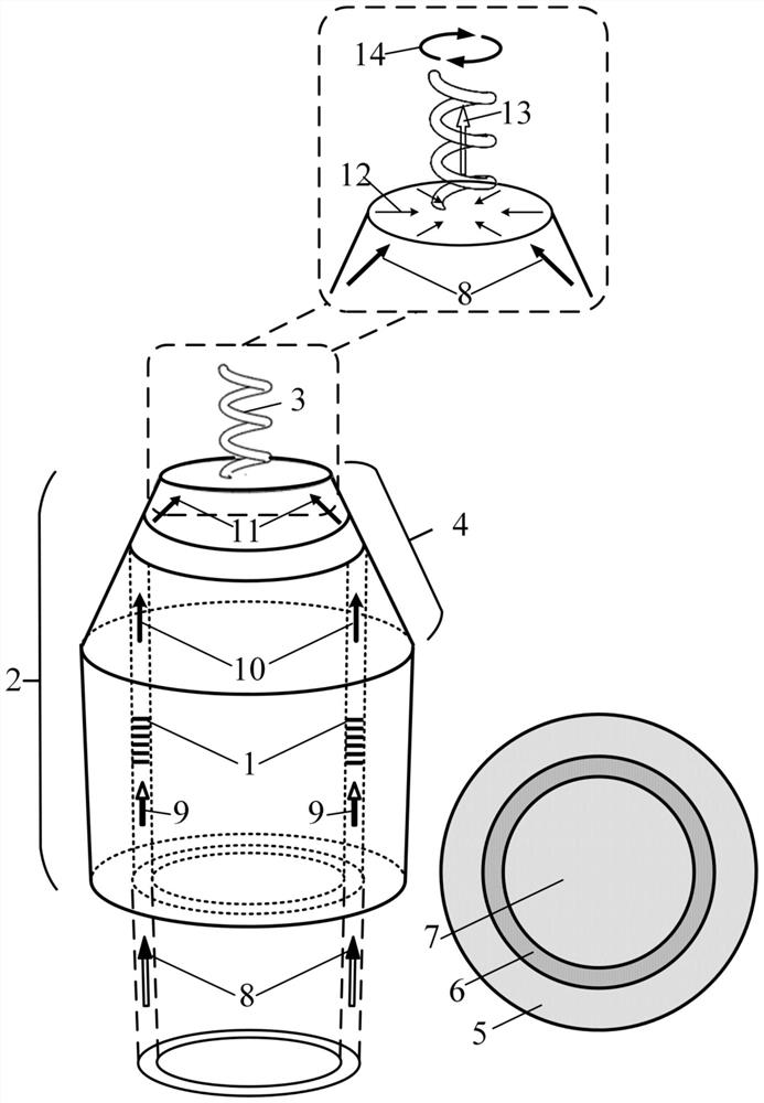
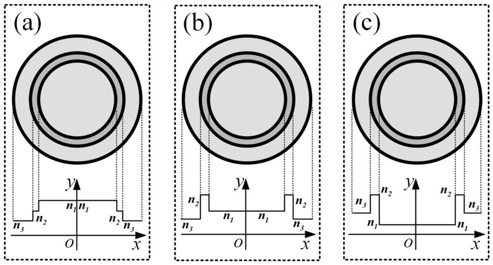
[0031] The embodiment of the present invention provides an optical fiber helical antenna wave field converter, which is characterized in that: the device is composed of a ring-core optical fiber 2 with a long-period fiber grating 1, and a helical antenna 3 in the center of the fiber end; wherein, the ring-core The fiber end of the optical fiber 2 is ground to form a truncated cone 4 at the fiber end, and the ring-core fiber 2 includes an outer cladding 5, a ring-shaped core 6, and an inner cladding 7; the input light 8 is injected into the ring-core fiber 2 to form a low-order conduction mode 9, and the After modulation, the long-period fiber grating 1 is converted into a radially polarized mode 10 and transmits through the fiber-end truncated cone 4. Total internal reflection occurs at the interface between the outer cladding 5 and the external medium, and the reflected light wave 11 diffracts and transmits in the fiber-end cladding to reach The end face of the fiber end is th...


PUM


Abstract

The invention provides an optical fiber helical antenna wave field converter. The optical fiber helical antenna wave field converter is characterized by consisting of a section of annular core optical fiber 2 with a long-period fiber grating 1 and a helical antenna 3 in the center of a fiber end, wherein the fiber end of the annular core optical fiber 2 is ground to form a fiber end cone frustum 4, and the annular core optical fiber 2 comprises an outer cladding 5, an annular fiber core 6 and an inner cladding 7; input light 8 is injected into the annular core fiber 2 to form a low-order conduction mode 9, modulated by the long-period fiber grating 1 and converted into a radial polarization mode 10, total internal reflection occurs at an interface of the outer cladding 5 and an external medium when the input light is transmitted through the fiber end cone frustum 4, and reflected light waves 11 are diffracted in the fiber end cladding and transmitted to the end face of the fiber end and then focused at the fiber end; constructive interference 12 is generated at the focusing position, so that a longitudinal polarized light field 13 with enhanced interference is generated at the center of the fiber end, and the longitudinal polarized light field 13 outputs a circular polarized light field 14 after being modulated by the spiral antenna 4. The optical fiber helical antenna wave field converter can be applied to the fields of wave field conversion, signal detection, light control and the like.

Description

(1) Technical field [0001] The invention provides an optical fiber helical antenna wave field converter, which can be used in the fields of wave field conversion, light manipulation and the like. (2) Background technology [0002] The microstructure of the fiber end is an emerging optical manipulation platform, which can realize functions such as light conversion, light coupling, beam shaping, and optical sensing at the nanoscale. It is an efficient method to combine optical fiber with micro-nano technology. . Thanks to the miniature size and ultra-high aspect ratio of the fiber end cross-section, it is possible to work in remote and confined environments, while the biocompatibility and high mechanical strength of the fiber end make it a versatile material and special It is the perfect choice for the integrated platform of the structure, and at the same time, it also creates unparalleled opportunities for the realization of advanced fiber optic devices. Since the beginning...

Claims


Application Information

Patent Timeline
Patent Type & Authority Applications(China)
IPC IPC(8): G02B6/124G02B6/126G02B6/26
CPCG02B6/124G02B6/126G02B6/262
Inventor 邓洪昌罗中岳赵子惠张文涛苑立波
Owner GUILIN UNIV OF ELECTRONIC TECH
Learn More