Pipeline welding opening supporting equipment

A technology for supporting equipment and welding joints, which is applied in the field of supporting equipment for pipeline welding joints, which can solve problems such as disconnection, dislocation of welding points of steel pipes, rolling of steel pipes, etc., and achieve the effects of ensuring heat dissipation, improving air circulation, and improving stability

Active Publication Date: 2021-11-23
通力液压科技南通有限公司
View PDF5 Cites 1 Cited by
  • Summary
  • Abstract
  • Description
  • Claims
  • Application Information

AI Technical Summary

Problems solved by technology

[0003] During the steel pipe welding process, it is usually necessary to use supporting equipment to support the welding ends of the two steel pipes to achieve labor-saving effect, and in the welding process, the steel pipes need to be rotated, so the steel pipes on the top of the supporting equipment usually cannot get much If the steel pipe is well fixed, it is easy to roll during the welding process of the steel pipe, which will affect the welding effect; at the same time, when the steel pipe is manually controlled to rotate on the top of the support device, it is necessary to lift the steel pipe and then rotate it or directly roll the two steel pipes. At this time, two steel pipes may appear. If the vertical force or rotational force of the root steel pipe is not equal, because the welding point is still in an unstable state at high temperature, it will cause the welding point of the steel pipe to be dislocated or disconnected, which will have a greater impact on the final welding effect of the steel pipe

Method used


Image

  • Pipeline welding opening supporting equipment
  • Pipeline welding opening supporting equipment
  • Pipeline welding opening supporting equipment

Examples


Embodiment 1

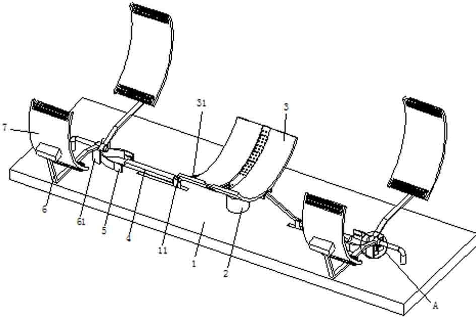
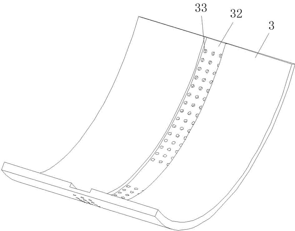
[0031] see Figure 1-2 , the present invention provides a technical solution: a pipe welding port support equipment, including a bottom plate 1 placed, the top center of the bottom plate 1 is connected to the center of the bottom of the support arc plate 3 through an elastic telescopic support column 2, and the support arc plate 3 is two The side bottoms are respectively hinged with two hinged transmission rods 31 at one end, and the other end of the hinged transmission rods 31 is hinged with the top of the slide block 11. One end of the push column 4 is fixed, and the other end of the push column 4 is installed on one side of the control spreader frame 5, and the other side of the control spreader frame 5 is in contact with the adjacent side of the two matching bars 61, and the side of the tie bar 61 near the control spreader frame 5 is Convex arc-shaped surface, and the contact part of the control spreader frame 5 and the matching strip 61 is also arranged on the convex arc-...

Embodiment 2

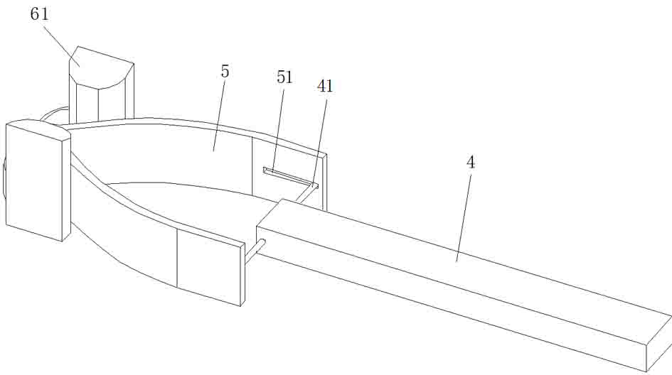
[0035] see figure 1 , image 3 , Figure 4 and Figure 5 , on the basis of Embodiment 1, in this embodiment, the control spreader frame 5 is in a "V" shape, the push column 4 is located between the two endpoints on the same side of the control spreader frame 5, and the front and rear sides of the push column 4 Both sides are fixed with sliding rod 41, and sliding rod 41 is slidingly connected with the chute 51 that is opened on the inside of control stretching frame 5, and the straight part is arranged on control stretching frame 5, and the straight part of control stretching frame 5 is positioned at the control stretching frame. 5 at the two endpoints on the same side, the chute 51 is set on the inner side of the straight part of the control spreader 5 and the length is less than the length of the straight part of the control spreader 5, and the center of the side where the matching strip 61 contacts the control spreader 5 is also A straight part is provided; by setting th...

Embodiment 3

[0038] see figure 1 , Figure 6 and Figure 7 , on the basis of Embodiment 1, in this embodiment, positioning rollers 8 are mounted on both ends of the wrapping positioning arc plate 7 for rotation, the positioning rollers 8 are made of rubber, and the surface of the positioning rollers 8 has a plurality of resistance increasing concave Groove 81, increasing resistance groove 81 comprises an arc portion and a straight portion, and the arc portion in the resistance increasing groove 81 between two parcel positioning arc plates 7 is positioned at the bottom of the straight portion; The roller 8 can position the steel pipe, and when the steel pipe rotates, the rotation of the positioning roller 8 will reduce the resistance when the steel pipe rotates. At the same time, setting the resistance increasing groove 81 can increase the friction between the positioning roller 8 and the outer wall of the steel pipe. , to ensure that the positioning roller 8 will rotate when the steel pi...


PUM


Abstract

The invention discloses pipeline welding opening supporting equipment, and relates to the technical field of pipeline welding. The pipeline welding opening supporting equipment comprises a containing bottom plate, the center of the top of the containing bottom plate is connected with the center of the bottom of a supporting arc plate through an elastic telescopic supporting column, and the bottoms of the two sides of the supporting arc plate are hinged to one ends of two hinged transmission rods correspondingly. According to the pipeline welding opening supporting equipment, by arranging the supporting arc plate, a supporting function can be achieved on welding end openings of two steel pipes, meanwhile, the supporting arc plate can descend under the action of the steel pipes, two wrapping and positioning arc plates move in the opposite directions through a pushing column by controlling an opening frame and cooperation strips, the two ends of the two wrapping and positioning arc plates abut against the outer walls of the steel pipes, the situation that the steel pipes roll on the top of the supporting arc plate in the welding process is avoided, meanwhile, when the steel pipes are rotated, the two ends of the two wrapping and positioning arc plates can achieve a limiting effect on the steel pipes, and the situation that the two steel pipes are staggered is avoided.

Description

technical field [0001] The invention relates to the technical field of pipeline welding, in particular to a pipeline welding joint supporting device. Background technique [0002] A pipeline is a device used to transport gas, liquid or fluid with solid particles connected by pipes, pipe connectors and valves; during the use of some steel pipes, welding equipment may be used to directly weld two steel pipes to Increase the length of the pipeline to meet the use of some scenarios. [0003] During the steel pipe welding process, it is usually necessary to use supporting equipment to support the welding ends of the two steel pipes to achieve labor-saving effect, and in the welding process, the steel pipes need to be rotated, so the steel pipes on the top of the supporting equipment usually cannot get much If the steel pipe is well fixed, it is easy to roll during the welding process of the steel pipe, which will affect the welding effect; at the same time, when the steel pipe i...

Claims


Application Information

Patent Timeline
IPC IPC(8): B23K37/053B23K37/00
Inventor 冯炳泉
Owner 通力液压科技南通有限公司
Why Eureka
Try Eureka