Adjustable tool mechanism for pipeline welding

An adjustable and pipeline technology, applied in the direction of welding equipment, auxiliary welding equipment, welding/cutting auxiliary equipment, etc., can solve the problems of the whole pipeline welding, inconvenient disassembly and installation, and the adjustment angle cannot be changed, so as to achieve fast splicing and fixing , easy to install and disassemble, change the bulky effect

Pending Publication Date: 2021-11-23
JIANGSU MARITIME INST
View PDF6 Cites 0 Cited by
  • Summary
  • Abstract
  • Description
  • Claims
  • Application Information

AI Technical Summary

Problems solved by technology

[0005] The object of the present invention is to provide an adjustable tooling mechanism for pipeline welding to solve the problem that some long-distance iron pipelines proposed in the above background technology are welded. The overall welding is relatively heavy because the pipeline is relatively heavy. It is more troublesome. When welding, there is no adjustable tooling mechanism that can weld the entire pipeline well. It is impossible to place the pipeline on the functional structure and then perform overall welding through the integration of the electric welding device. Welding cannot be adjusted at multiple angles at the same time during the overall operation. Such adjustment angles cannot be changed, so that the entire pipeline cannot be welded more accurately during welding. At the same time, the general adjustable tooling structure is in the When performing welding operations, due to the bulky structure of the tooling, it is not easy to disassemble and install, and the overall use is relatively troublesome, and it cannot be well applied to various environments.

Method used


Image

  • Adjustable tool mechanism for pipeline welding
  • Adjustable tool mechanism for pipeline welding
  • Adjustable tool mechanism for pipeline welding

Examples


Embodiment Construction

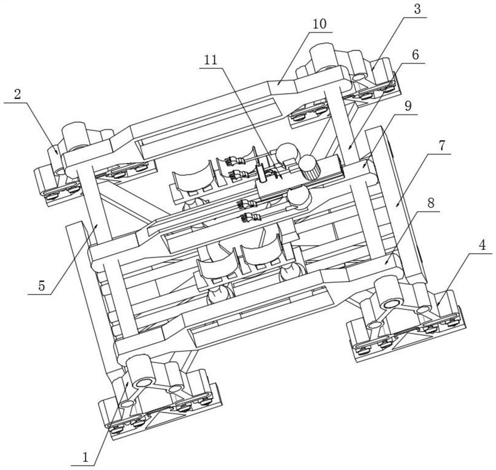
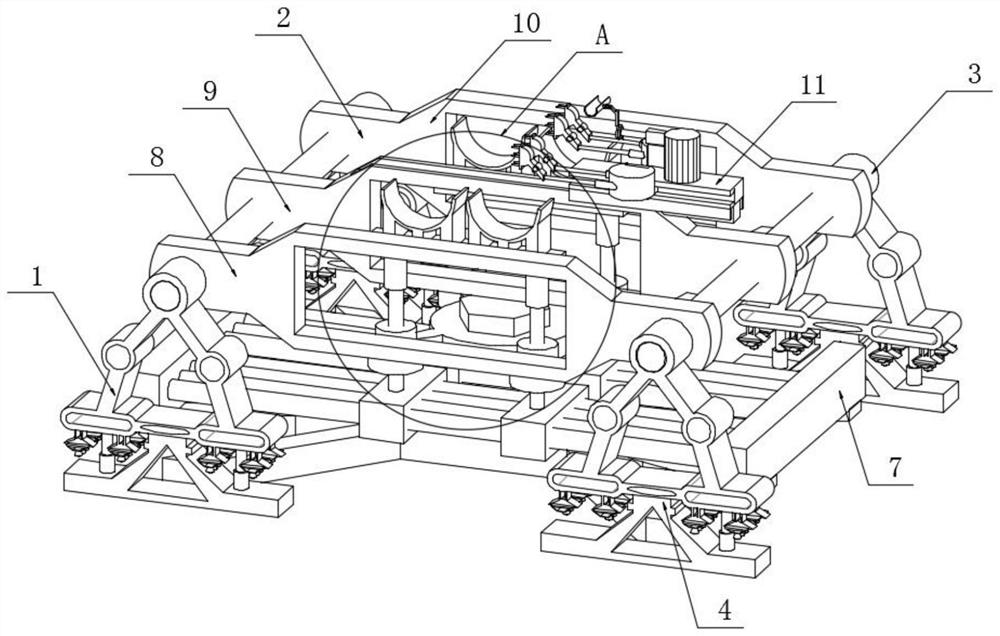
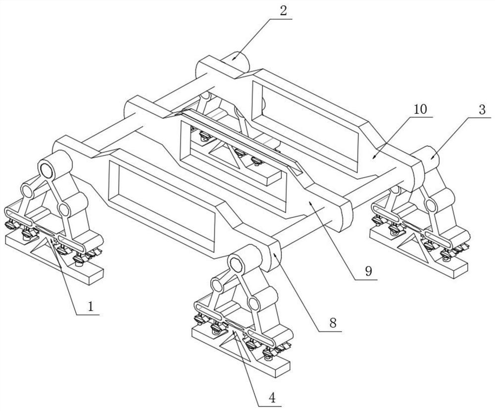
[0031] see Figure 1-9 , in an embodiment of the present invention, an adjustable tooling mechanism for pipeline welding, including a primary support mechanism 1, a plug-in fixing rod A5 and a pipeline support mechanism 7, the pipeline support mechanism 7 mainly supports the pipeline, and the primary support mechanism 1 is plugged with a plug-in fixed rod A5, and the other end of the plug-in fixed rod A5 is plugged with the secondary support mechanism 2, and the plug-in fixed rod A5 and the plug-in fixed rod B6 can facilitate the fixing of the partition plate-8, The fixing of the fixed partition plate 2 9 and the fixed partition plate 3 10 can simultaneously enable the first-level support mechanism 1, the second-level support mechanism 2, the third-level support mechanism 3 and the fourth-level support mechanism 4 to be better socketed and inserted. The outer wall of the fixed rod A5 is socketed with a fixed partition one 8, a fixed partition two 9 and a fixed partition three ...


PUM


Abstract

The invention discloses an adjustable tool mechanism for pipeline welding, and relates to the field of pipeline welding. The adjustable tool mechanism comprises a first-stage supporting mechanism, an insertion fixing rod A and a pipeline supporting mechanism, the insertion fixing rod A is inserted into the first-stage supporting mechanism, and the other end of the insertion fixing rod A is connected with a second-stage supporting mechanism in an inserted manner; and the outer wall of the insertion fixing rod A is sleeved with a first fixing partition plate, a second fixing partition plate and a third fixing partition plate. According to the adjustable tool mechanism, when precise welding is carried out, vibration detection of pipelines can be carried out, vibration between the pipelines is avoided, and it can be effectively guaranteed that the whole is more stable when the pipelines are welded; and when the whole is transported and used, rapid splicing and fixing can be carried out, overall installation and detachment are more convenient, the characteristic that a traditional tool is heavy in structure is changed, overall use is relatively convenient, and the tool can be suitable for various environments.

Description

technical field [0001] The invention relates to the field of pipeline welding, in particular to an adjustable tooling mechanism for pipeline welding. Background technique [0002] A pipeline is a device used to transport gas, liquid or fluid with solid particles connected by pipes, pipe connectors and valves. Usually, after the fluid is pressurized by blowers, compressors, pumps and boilers, it flows from the high-pressure part of the pipeline to the low-pressure part, and it can also be transported by the pressure or gravity of the fluid itself. Pipes are widely used, mainly in water supply, drainage, heat supply, gas supply, long-distance transportation of oil and natural gas, agricultural irrigation, hydraulic engineering and various industrial devices. Pipeline refers to the device used to transport gas, liquid or fluid with solid particles connected by pipes, pipe connectors and valves. Usually, after the fluid is pressurized by blowers, compressors, pumps and boilers...

Claims


Application Information

Patent Timeline
IPC IPC(8): B23K37/053B23K37/00
CPCB23K37/053B23K37/00B23K2101/06Y02P70/10
Inventor 张强勇赵先锐董乃涵陈勇刘桂香朱征宇白津生贾向东毛琪钦康猛裴先峰
Owner JIANGSU MARITIME INST
Why Eureka
Try Eureka