Soil remediation agent filling device
A soil remediation and filling device technology, which is applied in the field of soil remediation, can solve problems such as uneven mixing, achieve the effects of increasing mixing efficiency, facilitating soil remediation, and increasing the range of mixing
- Summary
- Abstract
- Description
- Claims
- Application Information
AI Technical Summary
Problems solved by technology
Method used
Image
Examples
Embodiment 1
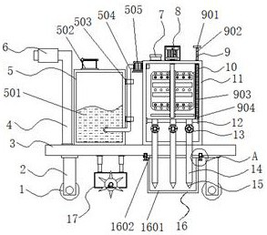
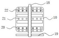
[0035] Example 1: See Figure 1-6 , a soil remediation agent filling device, comprising casters 1, support columns 2 and a base plate 3, the four corners of the bottom of the base plate 3 are respectively fixedly connected with support columns 2, and the bottom ends of the support columns 2 are provided with casters 1, base plate 3 One side of the top is provided with a water inlet mechanism 5, and the other side of the top of the bottom plate 3 is provided with a filling box 11, and the bottom end inside the filling box 11 is fixedly connected with a baffle plate 12, and the bottom end of the baffle plate 12 is provided with a medicine discharge mechanism. Pipe 14, a valve 13 is provided at one end of the drug delivery pipe 14, a drug delivery nozzle 15 is provided at the bottom of the drug delivery tube 14, a soil turning mechanism 17 is provided at one side of the bottom end of the bottom plate 3, and a Protective structure 16, one side of the top of the bottom plate 3 is f...
Embodiment 2
[0039] Embodiment 2: The water inlet mechanism 5 is composed of a water tank 501, a water inlet 502, a limit block 503, a water pipe 504 and a water pump 505. The water tank 501 is arranged on one side of the top of the bottom plate 3, and the water pump 505 is arranged on the side of the filling tank 11. At the top, the model of the water pump 505 is BJZ037, and the output end and the output end of the water pump 505 are respectively provided with water pipes 504, and one side of the top of the water tank 501 is fixedly connected with a water inlet 502, and the bottom end and the top end of the water tank 501 are respectively fixedly connected with limited bit block 503;
[0040] One side of the water pipe 504 runs through the filling tank 11, and the other side of the water pipe 504 runs through the inside of the water tank 501 and extends to the bottom of the water tank 501;
[0041] Specifically, such as figure 1 As shown, in order to prevent the clean water inside the fi...
Embodiment 3
[0042] Embodiment 3: The easy-to-observe structure 9 is made up of a pull block 901, a floating plate 902, a limiting groove 903 and a floating ball 904. The limiting groove 903 is arranged on one side inside the filling tank 11, and the inside of the limiting groove 903 is provided with The floating plate 902, the bottom end of the floating plate 902 is fixedly connected with a floating ball 904, and the top end of the floating plate 902 is fixedly connected with a pull block 901;
[0043] The outside of the floating ball 904 is provided with several groups of water inlet tanks, and the external diameter of the floating plate 902 is smaller than the internal diameter of the floating ball 904;
[0044] Specifically, such as figure 1 As shown, a limiting groove 903 is provided on one side inside the filling tank 11, and the medicament inside the filling tank 11 can enter the inside of the limiting groove 903 through the water inlet hole outside the limiting groove 903, because ...
PUM
 Abstract
Description
Claims
Application Information
 - R&D Engineer
- R&D Manager
- IP Professional
- Industry Leading Data Capabilities
- Powerful AI technology
- Patent DNA Extraction
Browse by: Latest US Patents, China's latest patents, Technical Efficacy Thesaurus, Application Domain, Technology Topic, Popular Technical Reports.
© 2024 PatSnap. All rights reserved.Legal|Privacy policy|Modern Slavery Act Transparency Statement|Sitemap|About US| Contact US: help@patsnap.com


