
Horizontal rotary reaction device

A reaction device, horizontal technology, applied in the field of horizontal rotary reaction device, can solve the problems of high spare parts cost and operation cost, serious system heat energy loss, low production efficiency, etc., achieve low equipment maintenance and operation cost, and heat energy utilization efficiency High, high production efficiency effect

Pending Publication Date: 2021-11-23
JINCHUAN GROUP LIMITED
View PDF0 Cites 0 Cited by
  • Summary
  • Abstract
  • Description
  • Claims
  • Application Information

AI Technical Summary

Problems solved by technology

[0002] The traditionally used horizontal reaction device, after high temperature and high pressure reaction, the slurry must pass through the flash valve for pressure relief and cooling, the cost of spare parts is high, the heat loss of the system is serious, and the effective heat energy utilization rate is low; each compartment of the system is equipped with a stirring It is easy to cause the leakage of high-pressure strong acid, which is not conducive to safe operation; it is easy to form scaling in the compartment and the liquid outlet position; it must be stopped for descaling and maintenance, the cost of spare parts and operation is high, and the production efficiency is low

Method used


Image

  • Horizontal rotary reaction device
  • Horizontal rotary reaction device
  • Horizontal rotary reaction device

Examples


Embodiment

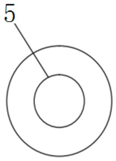
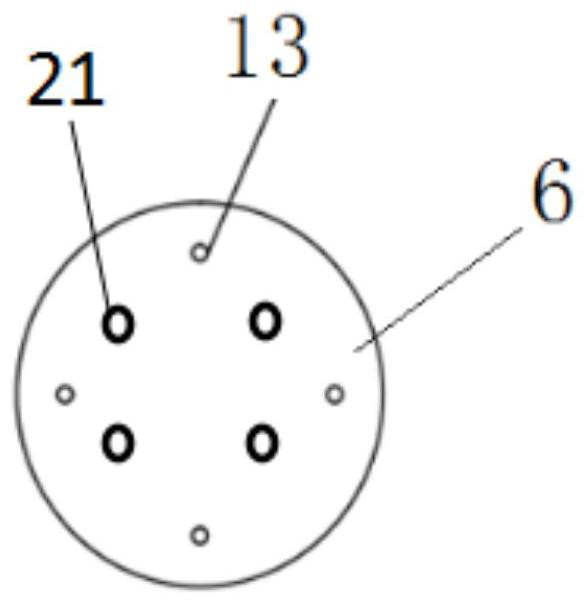
[0038]The low-temperature slurry enters the heat exchange zone 22 through the liquid inlet pipe 2 at a temperature of 30°C and a pressure of 1 MPa. After passing through the through holes in the middle of several baffles 5, the liquid inlet speed is effectively controlled. The temperature of the slurry absorbs heat and rises, and the slurry passes through the first separator. The first low-temperature liquid inlet 13 on 6, the low-temperature liquid inlet pipe 9 and the second low-temperature liquid inlet 14 on the second partition enter the mixing zone 24, and the temperature of the slurry and the inlet pipe 4 is 250°C, and the pressure is The saturated steam of 4.0 MPa is fully mixed in the mixing zone 24, and the mixed slurry enters the reaction zone 23 through the mixed solution outlet 15 on the second partition 7 under pressure, and the high-temperature and high-pressure slurry is fully reacted in the reaction zone 23 The temperature is 220-230°C and the pressure is 3.0-3....


PUM


Abstract

A horizontal rotary reaction device comprises a reactor cylinder, a liquid inlet pipe, a liquid outlet pipe, a gas inlet pipe, a driving device and a supporting device; the two ends of the reactor cylinder are connected with rotary joints, a baffle, a first partition plate and a second partition plate which are vertically arranged are sequentially arranged in the reactor cylinder, and the first partition plate is connected with the second partition plate through a low-temperature liquid inlet pipe; one end of the liquid inlet pipe extends into the cylinder from the front end of the reactor cylinder, the liquid outlet pipe is located in the reactor cylinder, the liquid inlet end of the liquid outlet pipe is connected with the first partition plate, and the liquid outlet end of the liquid outlet pipe extends out of the cylinder from the front end of the reactor cylinder; the gas outlet end of the gas inlet pipe extends into the cylinder from a rotary joint at the tail end of the reactor cylinder; and the driving device is used for driving the reactor cylinder to rotate, and the supporting device is arranged below the reactor cylinder. Slurry mixing, reaction and heat exchange can be carried out synchronously, the driving device drives the reactor to rotate, stirring is uniform, the surface of the cylinder is not prone to scaling, the heat energy utilization efficiency is high, and cost is low.

Description

technical field [0001] The invention belongs to the field of metallurgical equipment, in particular to a horizontal rotary reaction device. Background technique [0002] The traditionally used horizontal reaction device, after high temperature and high pressure reaction, the slurry must pass through the flash valve for pressure relief and cooling, the cost of spare parts is high, the heat loss of the system is serious, and the effective heat energy utilization rate is low; each compartment of the system is equipped with a stirring It is easy to cause the leakage of high-pressure strong acid, which is not conducive to safe operation; it is easy to form scaling in the compartment and the liquid outlet position; it must be stopped for descaling and maintenance, the cost of spare parts and operation is high, and the production efficiency is low. Contents of the invention [0003] Aiming at the deficiencies in the above-mentioned prior art, the present invention provides a hori...

Claims


Application Information

Patent Timeline
Patent Type & Authority Applications(China)
IPC IPC(8): B01J19/28B01J19/00B01J3/04
CPCB01J19/28B01J19/0053B01J19/006B01J19/0006B01J19/0013B01J3/04B01J2219/182B01J2219/00768B01J2219/00155B01J2219/00162
Inventor 陈小林贺来荣王贤来宗红星张鹏沙滨姚菲王多江边颖
Owner JINCHUAN GROUP LIMITED
Learn More