Coil device
A coil device, mounting surface technology, applied in the direction of transformer/inductor coil/winding/connection, preventing/reducing unwanted electrical/magnetic effects, core/yoke, etc.
- Summary
- Abstract
- Description
- Claims
- Application Information
AI Technical Summary
Problems solved by technology
Method used
Image

Examples
no. 1 approach
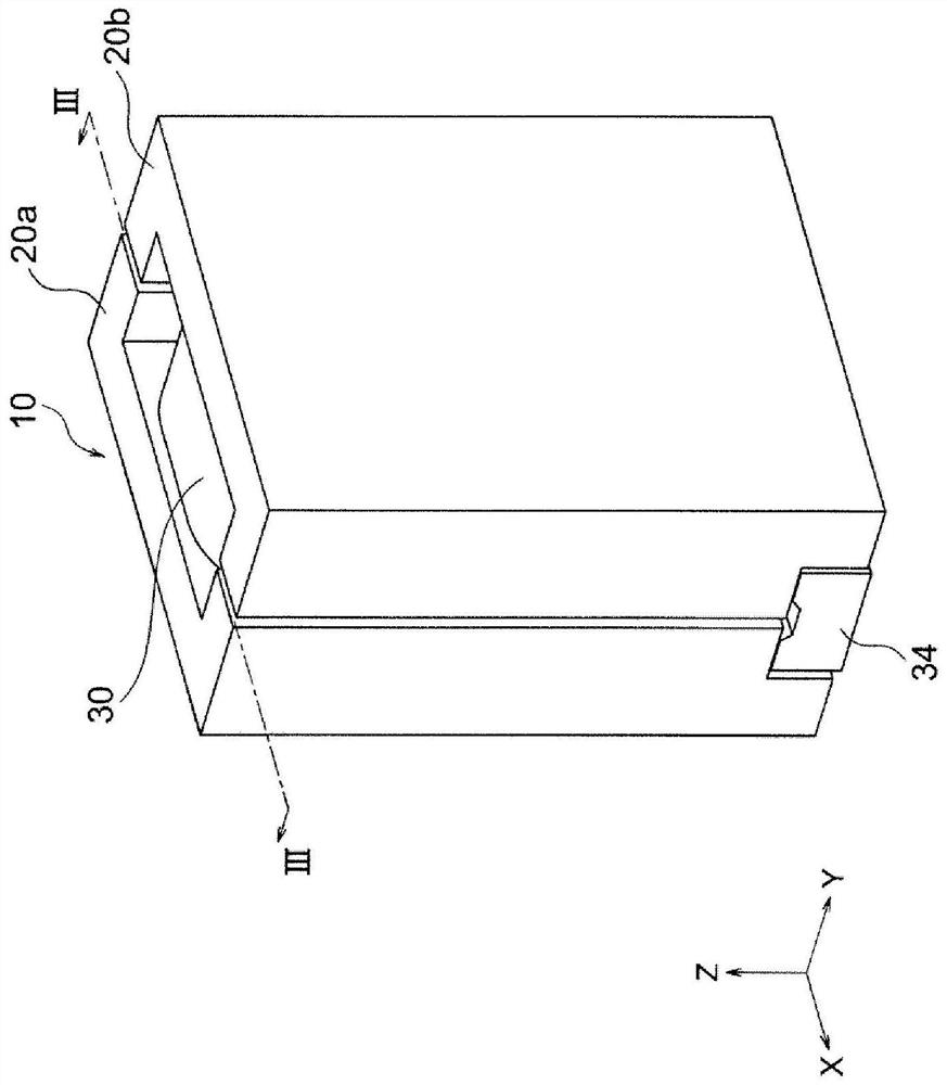
[0044] Such as Figure 1A As shown, the coil device 10 according to the first embodiment of the present invention has a substantially rectangular parallelepiped shape and functions as a coupling coil used in a power supply circuit or the like. The width of the coil device 10 in the X-axis direction is preferably 3.0-20.0 mm, the width in the Y-axis direction is preferably 3.0-20.0 mm, and the width in the Z-axis direction is preferably 3.0-20.0 mm.
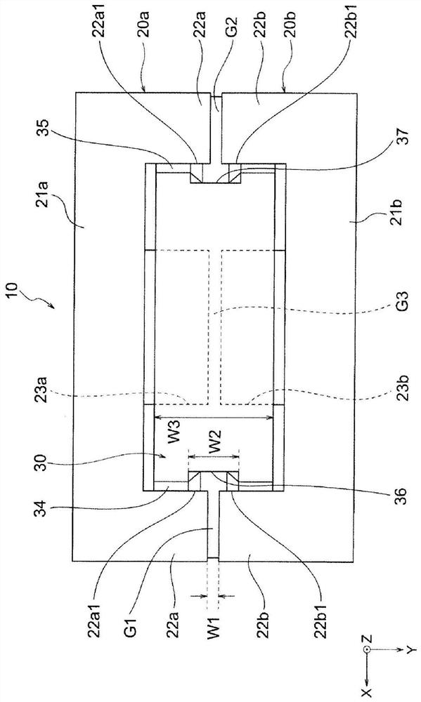
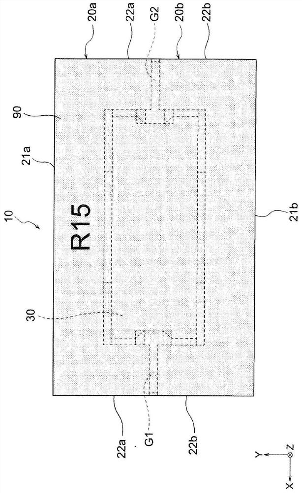
[0045] Such as figure 2 As shown, the coil arrangement 10 has a first core 20 a , a second core 20 b , a first conductor 30 and a second conductor 40 . Either one of the first conductor 30 and the second conductor 40 functions as a primary coil, and the other functions as a secondary coil. Details of the conductors 30, 40 will be described later.
[0046] The 1st core 20a and the 2nd core 20b each have the same shape, and are comprised by what is called an E shape. The 1st core 20a and the 2nd core 20b are arrange|positioned s...
no. 2 approach
[0119] The coil device 110 of the second embodiment of the present invention differs from the above-mentioned first embodiment only in the following points, and other configurations are the same as those of the above-mentioned first embodiment, and exhibit the same effects. In the drawings, members common to those of the first embodiment are denoted by common symbols, and descriptions of overlapping parts are omitted.
[0120] Such as Figure 4A and Figure 5 As shown, the coil device 110 has a first core 120 a , a second core 120 b , a first conductor 130 and a second conductor 40 . The first core 120a has a pair of first outer legs 122a, 122a, but does not have figure 2 The illustrated side groove portions 25a, 25b are different from the first core 20a of the first embodiment in this point. The length of the Z-axis direction of the 1st outer leg part 122a, 122a is extended by the amount which does not provide the side groove part 25a, 25b.
[0121]The second core 120b d...
no. 3 approach
[0141] The coil device 210 of the third embodiment of the present invention differs from the above-mentioned first embodiment only in the following points, and other configurations are the same as those of the above-mentioned first embodiment, and exhibit the same effects. In the drawings, members common to those of the first embodiment and the second embodiment are assigned common symbols, and descriptions of overlapping parts are omitted.
[0142] Such as Figure 7 As shown, the coil device 210 has a first core 120 a , a second core 220 b , a first conductor 30 and a second conductor 240 . The second core 220b has the same shape as the first core 120a.
[0143] Such as Figure 8 As shown, the second conductor 240 has a first mounting portion 244 and a second mounting portion 245 . Ends of the mounting parts 244 and 245 (each end of the second conductor 240 ) stand upward. Such as Figure 9 As shown, the end surfaces of the attachment parts 244, 245 are arranged at a pre...
PUM
| Property | Measurement | Unit |
|---|---|---|
| thickness | aaaaa | aaaaa |
| thickness | aaaaa | aaaaa |
Abstract
Description
Claims
Application Information
 - R&D
- Intellectual Property
- Life Sciences
- Materials
- Tech Scout
- Unparalleled Data Quality
- Higher Quality Content
- 60% Fewer Hallucinations
Browse by: Latest US Patents, China's latest patents, Technical Efficacy Thesaurus, Application Domain, Technology Topic, Popular Technical Reports.
© 2025 PatSnap. All rights reserved.Legal|Privacy policy|Modern Slavery Act Transparency Statement|Sitemap|About US| Contact US: help@patsnap.com