Non-tempering biomass feeding device and method capable of preventing tempering

A technology of biomass energy and feeding device, which is applied to the safety device of the combustion chamber, combustion method, fuel supply, etc., and can solve the problems of inlet blockage, danger-prone, insufficient combustion, etc., so as to prevent material blockage and transportation Too fast, the effect of internal resistance reduction

Inactive Publication Date: 2021-11-19
文亮
View PDF7 Cites 0 Cited by
  • Summary
  • Abstract
  • Description
  • Claims
  • Application Information

AI Technical Summary

Problems solved by technology

[0006] Aiming at the deficiencies of the prior art, the present invention provides a feeding device and method for preventing tempering of biomass without tempering, which is equipped with the ability to automatically push the material at the feed inlet to prevent clogging, and at the same time prevent excessively fast conveying, resulting in insufficient combustion of the material However, the current biomass burner is sometimes too long when feeding the material, which easily causes the entrance to be blocked at the entrance, which requires manual dredging, but the machine is always in the running state, which is also prone to occurrence Dangerous, at the same time, when the material is fully burned, sometimes due to the excessive feeding of the material, the combustion is not sufficient, and black smoke and dust will be emitted to the atmosphere, which is easy to pollute the atmosphere, so it is necessary to manually adjust the feed rate, which is more troublesome.

Method used


Image

  • Non-tempering biomass feeding device and method capable of preventing tempering
  • Non-tempering biomass feeding device and method capable of preventing tempering
  • Non-tempering biomass feeding device and method capable of preventing tempering

Examples


Embodiment Construction

[0038] The following will clearly and completely describe the technical solutions in the embodiments of the present invention with reference to the accompanying drawings in the embodiments of the present invention. Obviously, the described embodiments are only some, not all, embodiments of the present invention. Based on the embodiments of the present invention, all other embodiments obtained by persons of ordinary skill in the art without making creative efforts belong to the protection scope of the present invention.

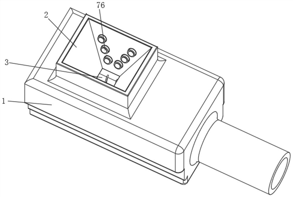
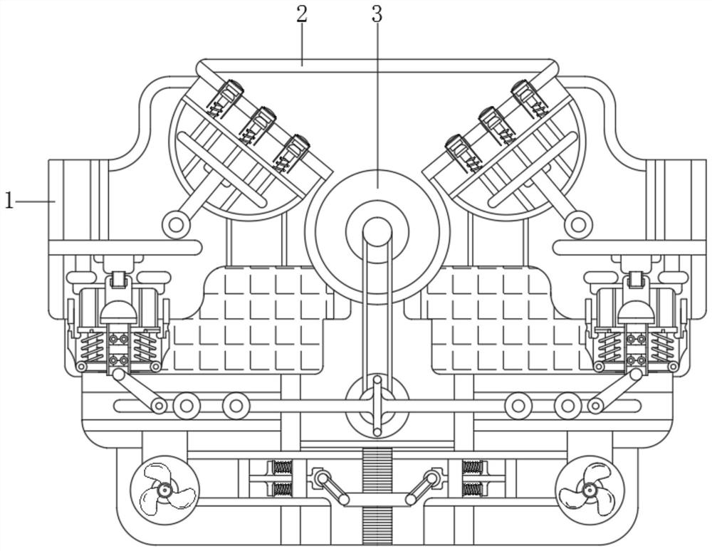
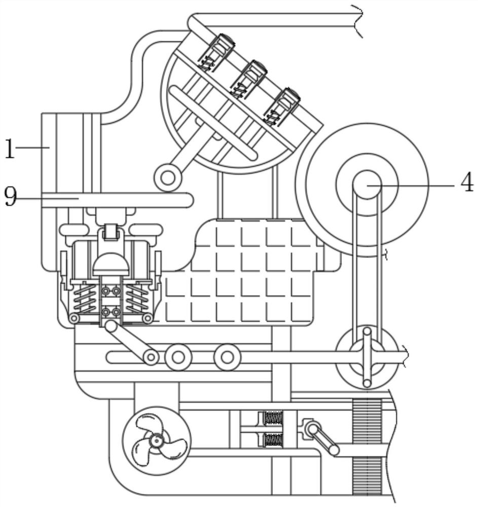
[0039] see Figure 1-6, the non-tempered biomass can prevent the feeding device from tempering, including the shell 1, the conversion mechanism 5, the transmission mechanism 6, the dredging mechanism 7 and the speed regulating mechanism 8, and the top of the shell 1 is provided with the feed port 2, the feed port 2 The lower end is movably connected to the conveying shaft 3, the front end of the conveying shaft 3 is fixedly connected to the rotating shaft 4, t...


PUM


Abstract

The invention relates to the technical field of burners, and provides a non-tempering biomass feeding device and method capable of preventing tempering. The non-tempering biomass feeding device capable of preventing tempering comprises a shell, a switching mechanism, a transmission mechanism, a dredging mechanism and a speed regulating mechanism, wherein a feeding port is formed in the top of the shell; a conveying shaft is movably connected to the lower end of the feeding port; a rotating shaft is fixedly connected to the front end of the conveying shaft; the lower end of the rotating shaft is movably connected with the switching mechanism; the left side of the switching mechanism is movably connected with the transmission mechanism; and the upper end of the transmission mechanism is movably connected with the bottom of the dredging mechanism. According to the non-tempering biomass feeding device and method capable of preventing tempering, large-size materials stacked in the feeding port are pushed upwards, small-size materials fall downwards in a gap, and due to the fact that a T-shaped rod reciprocates, an ejector block also reciprocates through the transmission effect of an internal structure, so that the effects that the materials are automatically dredged in the feeding process, and the situation that the materials are blocked to affect the machining efficiency is prevented are achieved.

Description

technical field [0001] The invention relates to the technical field of combustion machines, in particular to a feeding device and method for preventing tempering of non-tempering biomass. Background technique [0002] With the development of the times and the gradual improvement of people's living standards, modern times have entered the era of science and technology, making people pay more attention to the protection of the ecological environment. Among them, the combustion of some waste materials such as straw is now carried out by combustion machines, which can It is good to deal with some of the smoke and dust to prevent it from entering the atmosphere and polluting the environment. [0003] However, the current biomass burner sometimes has too long material when feeding, so it is easy to cause the entrance to be blocked at the entrance, which requires manual dredging, but the machine is always in operation, which is also prone to danger. When the material is fully burn...

Claims


Application Information

Patent Timeline
Patent Type & Authority Applications(China)
IPC IPC(8): F23K3/00F23B40/00F23M11/02
CPCF23K3/00F23B40/00F23M11/02
Inventor 文亮
Owner 文亮
Why Eureka
Try Eureka