Eureka AIR delivers breakthrough ideas for toughest innovation challenges, trusted by R&D personnel around the world.

Bistable electromagnetic valve

A solenoid valve, bistable technology, applied in the direction of lift valve, valve details, valve device, etc., can solve the problems of unsuitable solenoid valve, reduced force of the ejector rod pressing the valve port, copper loss, etc., which is beneficial to small The effect of reducing and reducing the size

Active Publication Date: 2021-11-19
ZHEJIANG UNIV
View PDF11 Cites 5 Cited by
  • Summary
  • Abstract
  • Description
  • Claims
  • Application Information

AI Technical Summary

Problems solved by technology

However, mechanical springs present two major drawbacks
First, with the increase of the opening times of the solenoid valve, the mechanical spring will inevitably fail. The force is reduced, so that the valve port seal is not reliable
Second, the energy consumption is large
Continuous power on can keep the valve open. In many occasions, the valve is open for a long time, and the disadvantage of energy consumption is more obvious. Moreover, long time power on will cause serious copper loss and cause serious heat generation in the valve.
In addition, the structure of the spring and the ejector rod is not conducive to the miniaturization of the solenoid valve. In the occasions with high space requirements, the traditional solenoid valve is obviously not suitable.

Method used


Image

  • Bistable electromagnetic valve
  • Bistable electromagnetic valve
  • Bistable electromagnetic valve

Examples


Embodiment Construction

[0027] The following will clearly and completely describe the technical solutions in the embodiments of the present invention with reference to the accompanying drawings in the embodiments of the present invention. Obviously, the described embodiments are only part of the embodiments of the present invention, not all of them. Based on the embodiments of the present invention, all other embodiments obtained by persons of ordinary skill in the art without creative efforts fall within the protection scope of the present invention.

[0028] It should be noted that all directional indications (such as up, down, left, right, front, back...) in the embodiments of the present invention are only used to explain the relationship between the components in a certain posture (as shown in the accompanying drawings). Relative positional relationship, movement conditions, etc., if the specific posture changes, the directional indication will also change accordingly.

[0029] Such as figure ...


PUM


Abstract

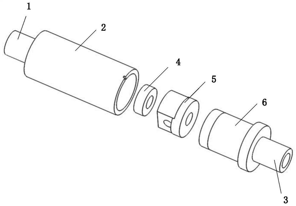
The invention discloses a bistable electromagnetic valve. The bistable electromagnetic valve comprises an air inlet pipe, a valve body and an air outlet pipe; a cylindrical cavity is formed in the valve body, and a fixed annular magnet, a moving assembly and an electromagnet are sequentially arranged in the cylindrical cavity in the direction from the air inlet end to the air outlet end; the moving assembly can move between the fixed annular magnet and the electromagnet in the axial direction of the cylindrical cavity; the moving assembly can seal a valve port under the attraction of the fixed annular magnet, so that the valve is kept in a normally off state; and when the valve is powered on, under attraction of the electromagnet, the moving assembly gets far away from the valve port and is attached to a cylindrical iron core of the electromagnet, the valve is opened, and the structure is a bistable structure. The bistable electromagnetic valve has the advantages that the problems that a traditional electromagnetic valve is low in reliability, large in energy consumption and difficult to miniaturize can be solved, the combination of a mechanical spring and an ejector rod is replaced with a magnetic spring, and therefore the reliability of the electromagnetic valve is improved, and meanwhile the energy consumption and the size of the electromagnetic valve are reduced; and in a micro electronic system, the bistable electromagnetic valve has great application potential.

Description

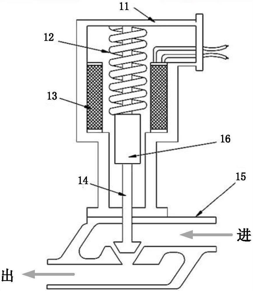
technical field [0001] The invention belongs to the field of electromagnetic valve equipment, and in particular relates to a bistable electromagnetic valve. Background technique [0002] Solenoid valve is widely used in various fluid control systems because of its simple structure and working principle. The structure of the traditional solenoid valve is as follows: figure 1 As shown, it mainly includes a valve body 11 , a return spring 12 , an electromagnetic coil 13 , a push rod 14 , a valve port 15 and an armature 16 . When not electrified, the ejector rod of the solenoid valve pushes against the conical valve port under the action of the spring force, so that the valve port is closed. When energized, the magnetic force generated by the coil attracts the armature to move upward against the spring force, and the valve port is opened. Continue to energize the solenoid valve to keep the solenoid valve open until the electromagnetic suction disappears when the power is turn...

Claims


Application Information

Patent Timeline
IPC IPC(8): F16K1/00F16K31/06
CPCF16K1/00F16K31/0655F16K31/0675
Inventor 韩冬卢方郑哲郇泉刘毅龚国芳杨华勇
Owner ZHEJIANG UNIV
Why Eureka
Eureka Blog
Learn More