Real-time anti-collision device of numerical control machine tool

A CNC machine tool and anti-collision technology, applied in the field of machine tools, can solve problems such as damage, and achieve the effect of high anti-collision safety factor

Active Publication Date: 2021-11-19
晨和晨智能装备(江苏)有限责任公司
View PDF6 Cites 1 Cited by
  • Summary
  • Abstract
  • Description
  • Claims
  • Application Information

AI Technical Summary

Problems solved by technology

[0003] The invention patent with the application number 201820200791.6 discloses an anti-collision knife device for a CNC milling machine. There is a horizontal plate, and a buffer plate is connected between the left and right two sets of support frames. The bottom of the horizontal plate is provided with a hydraulic cylinder, and the power output end of the bottom of the hydraulic cylinder is provided with a connecting plate. The left and right sides of the bottom of the connecting plate All are equipped with buffer springs, the center of the bottom of the connecting plate is provided with a spindle box, the bottom of the spindle box is provided with a spindle, the bottom of the spindle is provided with a tool, the connecting plate is driven by a hydraulic cylinder, and the connecting plate drives the spindle box to The down movement is decelerated by the buffer spring to prevent the tool from being too fast to directly hit the workpiece. The distance between the tool and the workpiece can be monitored through the proximity switch. When the tool exceeds the rated distance, the tool is braked by the control device and the alarm device It sounds to remind the staff to come over for maintenance, but the equipment cannot disconnect the power of the hydraulic cylinder, which will cause the tool to still have the power to move downward, and there is still the possibility of damage

Method used


Image

  • Real-time anti-collision device of numerical control machine tool
  • Real-time anti-collision device of numerical control machine tool
  • Real-time anti-collision device of numerical control machine tool

Examples


Embodiment Construction

[0024] The following will clearly and completely describe the technical solutions in the embodiments of the present invention with reference to the accompanying drawings in the embodiments of the present invention. Obviously, the described embodiments are only some, not all, embodiments of the present invention.

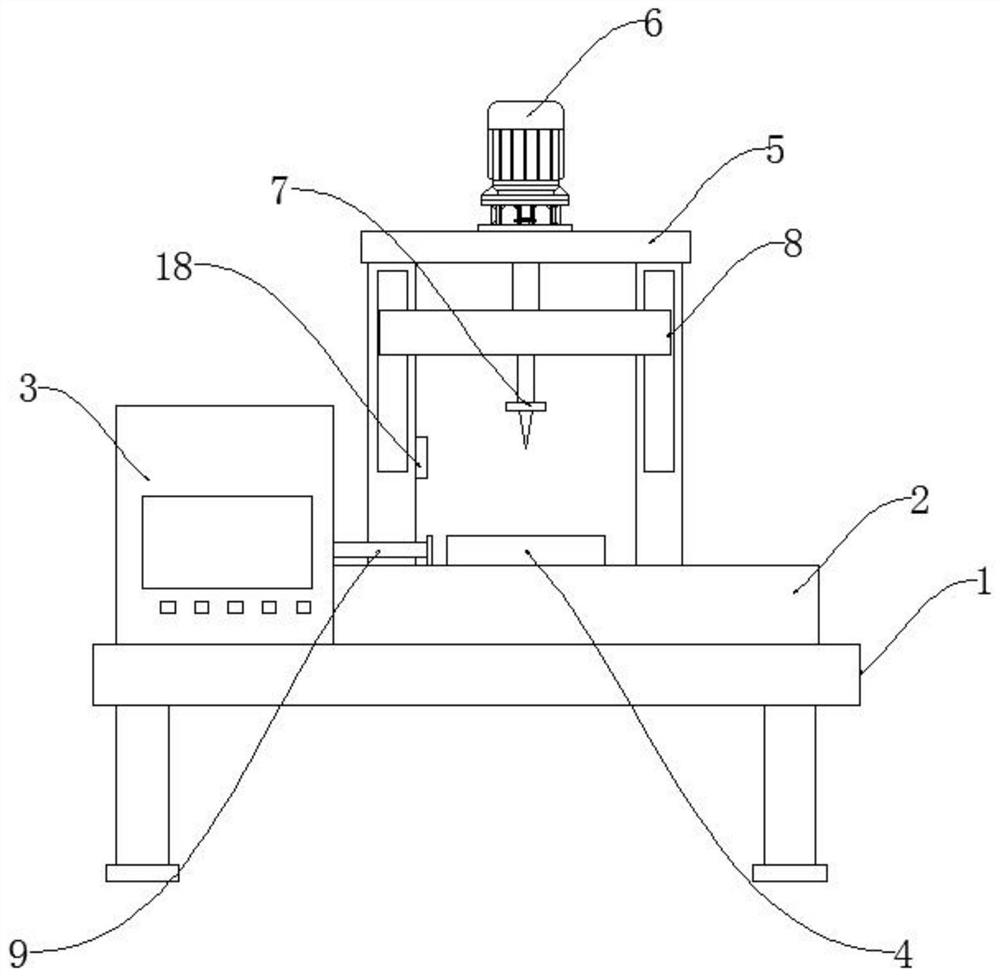
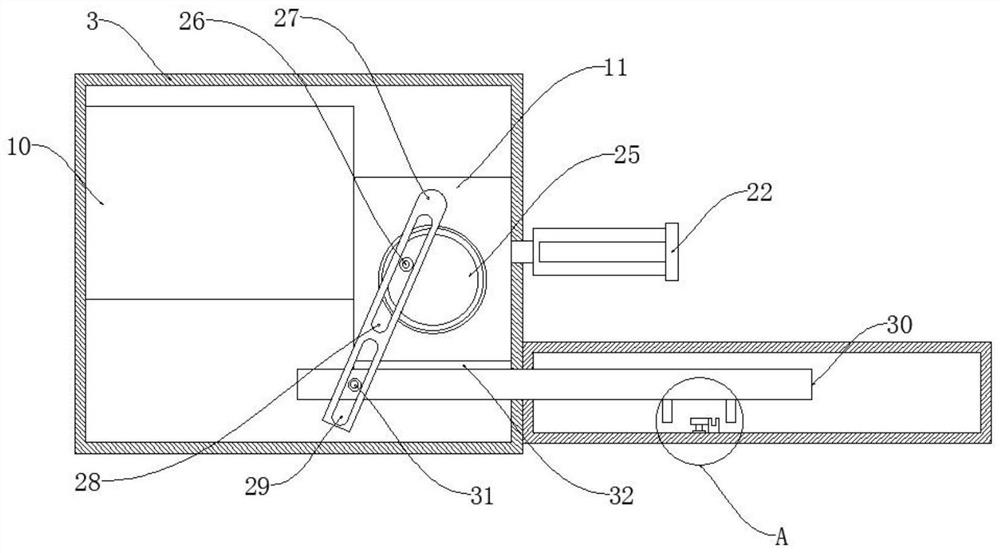
[0025] refer to Figure 1 to Figure 6 , a real-time anti-collision device for a numerically controlled machine tool, comprising a machine tool body 1, the top of the machine tool body 1 is provided with an object stage 2, and one end of the object stage 2 is provided with a cabinet 3, and the top of the object stage 2 The top is provided with a workpiece 4, and the top of the loading table 2 is fixedly connected with a support frame 5, and the top of the support frame 5 is provided with a vertical cylinder 6, and the telescopic shaft of the cylinder 6 is connected with a tool 7, so The casing 3 is provided with a cutting mechanism 9, and the cutting mechanism 9 inclu...


PUM


Abstract

The invention discloses a real-time anti-collision device of a numerical control machine tool. The real-time anti-collision device comprises a machine tool body, an objective table is arranged at the top of the machine tool body, a case is arranged at one end of the objective table, a workpiece is arranged at the top of the objective table, a supporting frame is fixedly connected to the top of the objective table, and a vertically-arranged air cylinder is arranged at the top end of the supporting frame; a cutter is connected to a telescopic shaft of the air cylinder, and a cutting-off mechanism is arranged in the case. According to the real-time anti-collision device, the cutting-off mechanism composed of a first part box, a second part box, a first gear, a movable plate, second clamping teeth, a second gear, a rotating disc, a first limiting column, a connecting plate, a reciprocating plate, a first push rod, a second push rod, a positive terminal, a rotating plate and a negative terminal is adopted, so that the power of a hydraulic cylinder can be rapidly and accurately cut off, the power source of the cutter is cut off, and the problem that the cutter still has power for downward movement due to the fact that the equipment cannot cut off the power of the hydraulic cylinder is effectively solved.

Description

technical field [0001] The invention relates to the technical field of machine tools, in particular to a real-time anti-collision device for a numerically controlled machine tool. Background technique [0002] Numerical control machine tool is the abbreviation of digital control machine tool, which is an automatic machine tool equipped with a program control system, which can logically process programs with control codes or other symbolic instructions, and decode them, using coded numbers It means that the numerical control device is input through the information carrier, and various control signals are sent out by the numerical control device after calculation and processing to control the movement of the machine tool, and automatically process the parts according to the shape and size required by the drawing. With the improvement, the utilization rate of CNC machine tools will also increase. [0003] The invention patent with the application number 201820200791.6 disclose...

Claims


Application Information

Patent Timeline
Patent Type & Authority Applications(China)
IPC IPC(8): B23Q11/00B23Q15/12
CPCB23Q11/00B23Q15/12Y02P70/10
Inventor 罗林杰
Owner 晨和晨智能装备(江苏)有限责任公司
Why Eureka
Try Eureka