
System and method for suppressing vibration of rotor in magnetic suspension bearing system

A technology of magnetic suspension bearing and rotor vibration, which is applied in magnetic bearing, restraining motor vibration control, bearing and other directions, which can solve the problems of error, inability to quickly reduce rotor impact and vibration, and inability of magnetic suspension bearing to provide active restraint force in time.

Pending Publication Date: 2021-11-16
江苏明磁动力科技有限公司
View PDF0 Cites 2 Cited by
  • Summary
  • Abstract
  • Description
  • Claims
  • Application Information

AI Technical Summary

Problems solved by technology

In the prior art, the research on the vibration suppression of the rotor caused by the disturbance force in the magnetic suspension bearing system has a large error in the compensation force observed only based on the displacement signal (it is greatly affected by the sampling frequency and the signal-to-noise ratio), and it is difficult to realize the random Accurate real-time compensation of disturbance force; for the study of system instability and resuspension caused by disturbance force, due to the large error in the analysis based on rotor displacement, the magnetic suspension bearing cannot provide appropriate active suppression force in time, and cannot quickly reduce the impact and impact of the rotor. Vibration, it is difficult to quickly realize the resuspension of the magnetic suspension bearing system

Method used


Image

  • System and method for suppressing vibration of rotor in magnetic suspension bearing system
  • System and method for suppressing vibration of rotor in magnetic suspension bearing system
  • System and method for suppressing vibration of rotor in magnetic suspension bearing system

Examples


Embodiment Construction

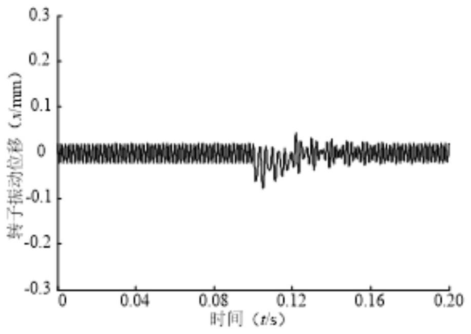
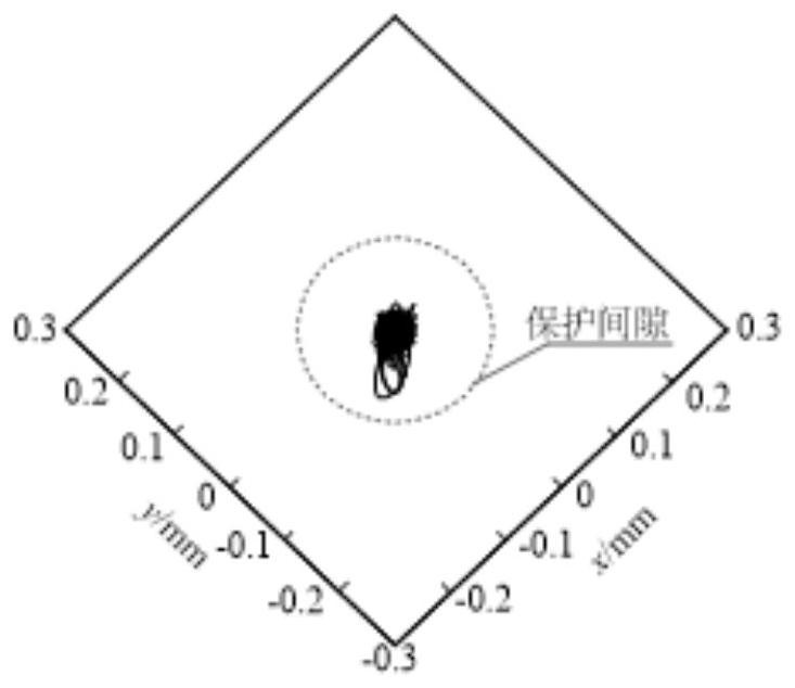
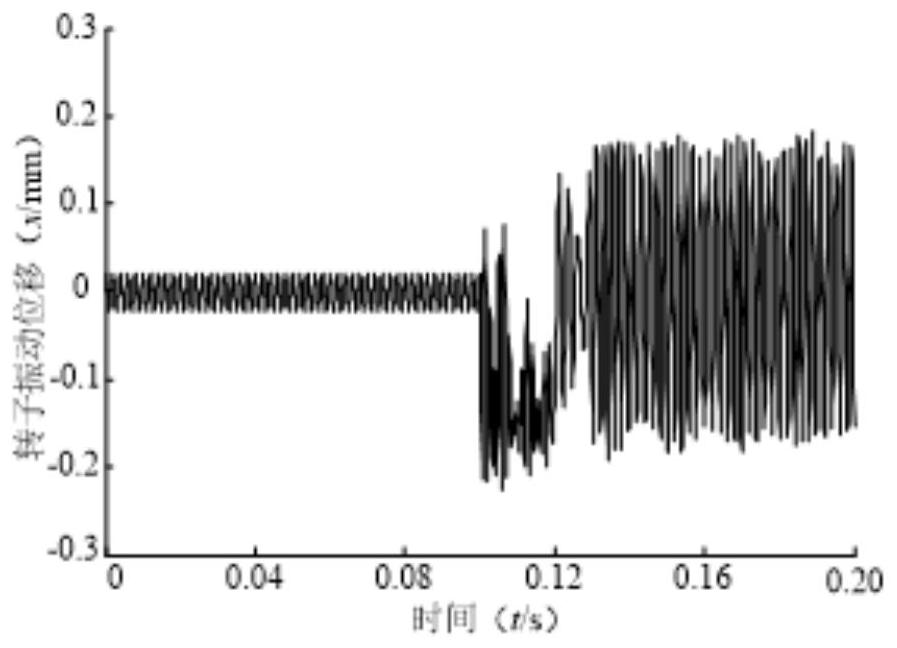
[0034] Such as Figure 5 As shown, a rotor vibration suppression system in a magnetic suspension bearing system includes: a magnetic suspension bearing system, a displacement sensor, a base acceleration feedforward compensator, a rotor disturbance compensation observer, a notch filter, a position controller, a power amplifier; a displacement The sensor is used to detect the rotor displacement; two differential circuits and a filter link are added to the conditioning circuit of the displacement sensor, and the rotor vibration displacement signal is differentiated twice to obtain the rotor vibration acceleration signal; the rotor disturbance compensation observer is used to receive the rotor vibration displacement signal, The rotor vibration acceleration signal, and send the rotor vibration suppression compensation control signal to the power amplifier; the power amplifier is used to adjust the control current of the magnetic suspension bearing; the base acceleration feedforward ...


PUM


Abstract

The invention belongs to the technical field of magnetic suspension bearings, and particularly relates to a rotor vibration suppression system and method in a magnetic suspension bearing system. When a rotor is subjected to an interference force, a rotor disturbance compensation observer sends a rotor vibration suppression compensation control signal after receiving a rotor vibration displacement signal and a rotor vibration acceleration signal; the control current is adjusted through a power amplifier, and electromagnetic force is provided; when the base is subjected to interference force, the base acceleration feed-forward compensator receives a base vibration acceleration signal and then sends a base acceleration feed-forward compensation signal, and then the position controller provides reference displacement; when the magnetic suspension bearing system is out of control, a position error control channel is cut off, a rotor vibration suppression control signal after instability is added, and full-gap vortex motion of the rotor in a protection bearing is suppressed; meanwhile, the rotor disturbance compensation observer sends a rotor vibration suppression compensation control signal, the control current of the magnetic suspension bearing is adjusted through the power amplifier, and electromagnetic force is provided.

Description

technical field [0001] The invention belongs to the technical field of magnetic suspension bearings, and in particular relates to a rotor vibration suppression system and method in a magnetic suspension bearing system. Background technique [0002] Magnetic suspension bearings are a new type of bearings that use electromagnetic force to achieve non-contact, and are often used in applications with high rotor speeds. At present, the magnetic suspension bearing control system basically adopts the control strategy based on the rotor position error, that is, the real-time vibration displacement of the rotor is detected by the displacement sensor, and the displacement error is obtained by comparing with the reference displacement, and then generated by the controller, the power amplifier, and the magnetic suspension bearing stator. Corresponding electromagnetic force to eliminate the displacement error. [0003] In the current control strategy, when the high-speed rotating rotor ...

Claims


Application Information

Patent Timeline
IPC IPC(8): H02P23/04H02P23/12H02P23/14H02P23/20H02N15/00F16C32/04
CPCH02P23/04H02P23/12H02P23/14H02P23/20H02N15/00F16C32/044
Inventor 朱益利于建英李渊张恒
Owner 江苏明磁动力科技有限公司
Learn More