
Novel dehumidification heat pump drying system

A drying system and dehumidification heat technology, applied in drying, drying machine, drying solid materials, etc., can solve the problems of reduced heat transfer efficiency, low heat transfer efficiency, high condensation and dehumidification wind speed, reduce circulating air volume, improve The effect of heat transfer efficiency

Pending Publication Date: 2021-11-16
上海尚禹环保科技有限公司
View PDF5 Cites 0 Cited by
  • Summary
  • Abstract
  • Description
  • Claims
  • Application Information

AI Technical Summary

Problems solved by technology

First, the specific heat capacity of hot air is small, the density of hot air is small, and the heat transfer efficiency of relying solely on hot air is low, and the air volume is large; The system needs to be equipped with a cooling fan or cooling water to discharge heat to the environment, resulting in low heat recovery efficiency; third, the high wind speed in the pipeline system caused by the large air volume during circulation makes the wind speed high during condensation and dehumidification, and the dehumidification effect is poor. The condensed water droplets are brought back into the return air again, and the excessively high wind speed will cause a large amount of dust in the circulating air, which will easily cause fouling on the surface of the evaporator and condenser, and reduce the heat transfer efficiency

Method used

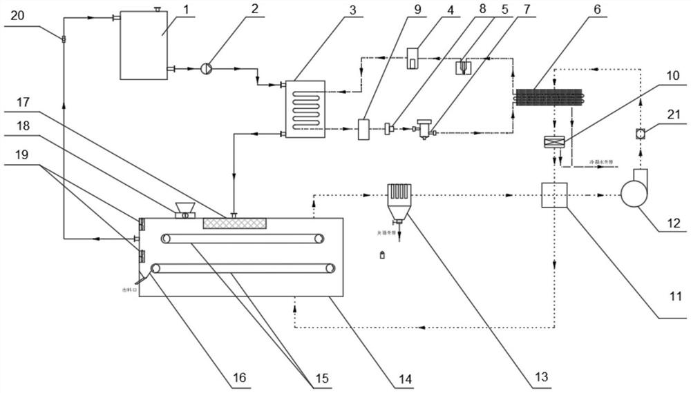

Image

  • Novel dehumidification heat pump drying system

Examples


Embodiment Construction

[0015] The following will clearly and completely describe the technical solutions in the embodiments of the present invention with reference to the accompanying drawings in the embodiments of the present invention. Obviously, the described embodiments are only some, not all, embodiments of the present invention. Based on the embodiments of the present invention, all other embodiments obtained by persons of ordinary skill in the art without making creative efforts belong to the protection scope of the present invention.

[0016] In the description of the present invention, it should be noted that the orientation or positional relationship indicated by the terms "vertical", "upper", "lower", "horizontal" etc. is based on the orientation or positional relationship shown in the drawings, and is only In order to facilitate the description of the present invention and simplify the description, it does not indicate or imply that the device or element referred to must have a specific o...


PUM


Abstract

The invention belongs to the field of dehumidification heat pump drying processes, and particularly discloses a novel dehumidification heat pump drying system. The system comprises a drying box, a hot water circulation pipeline module, a hot air circulation condensation dehumidification pipeline module, a heat pump working medium circulation pipeline module and a drying material distributing and conveying line, wherein the drying box is connected to the hot water circulation pipeline module through a flange interface, a flow meter is arranged on the hot water circulation pipeline, the hot water circulation pipeline module comprises a hot water tank, a hot water circulation pump, a condenser, a hot water radiator and a pipeline with the flow meter, a port of the hot water tank communicates with the hot water circulation pump through the pipeline, the hot water circulation pump is connected to the input end of the condenser, and heat is transferred to hot water through the condenser. According to the dehumidification heat pump drying system, two independent circulation systems of circulating hot water heat transfer and circulating hot air condensation and dehumidification are adopted, all heat is recycled, heat does not need to be directly discharged to the environment, and meanwhile the heat transfer efficiency and the dehumidification efficiency are greatly improved.

Description

technical field [0001] The invention relates to the field of dehumidification heat pump drying technology, in particular to a novel dehumidification heat pump drying system. Background technique [0002] The dehumidification heat pump drying process on the market mostly adopts hot air circulation drying, and its heat conduction only depends on the heat carried by the external circulation hot air, and the dehumidification mostly adopts direct external discharge of hot and humid air to the environment or external circulation of hot air condensation dehumidification. The external circulation mentioned here refers to the process in which the hot air leaves the drying box, enters the external heat pump piping system, and then returns to the drying box. Directly exhausting hot and humid air cannot recover the latent heat of evaporated water vapor, so the energy consumption is high. It is better to use the external circulation hot air condensation dehumidification process to save e...

Claims


Application Information

Patent Timeline
IPC IPC(8): F26B17/04F26B21/04F26B21/12F26B25/00F26B25/12F26B25/18
CPCF26B17/04F26B21/04F26B21/12F26B25/002F26B25/18F26B25/12Y02P70/10
Inventor 汪闰红李华芳李芳
Owner 上海尚禹环保科技有限公司
Learn More