
Synchronous belt transmission high-transmission-efficiency mechanical arm

A technology of synchronous belt transmission and transmission efficiency, applied in the directions of manipulators, claw arms, manufacturing tools, etc., can solve the problems of complex manufacturing, limited swing space of manipulators, time-consuming and laborious modeling, etc. The effect of limited angle and enhanced richness

Pending Publication Date: 2021-11-16
杭州太希智能科技有限公司
View PDF9 Cites 0 Cited by
  • Summary
  • Abstract
  • Description
  • Claims
  • Application Information

AI Technical Summary

Problems solved by technology

In addition, the current mechanical arm usually has multiple rotating joints. The rotation of each joint is realized by a stepper motor or a servo motor. A harmonic reducer and a cycloid reducer are often used at the end of the motor. There are reverse arc minutes during reverse motion, which is prone to errors, and the manufacturing is complicated and the processing cost is high. Since the manipulator is a complex system, there are uncertainties such as parameter perturbation, external interference, and unmodeled dynamics.
Therefore, there are uncertainties in the modeling model of the manipulator. For different tasks, it is necessary to plan the motion trajectory of the joint space of the manipulator, so as to cascade to form the terminal pose, so this will lead to multi-stage deceleration of the manipulator due to self-locking It is impossible to realize flexible drag teaching modeling, and the modeling corresponding to the adapted working environment is time-consuming and laborious, and there are few types of production lines to adapt to, which requires purchasing more sets, which will lead to higher costs. Due to the friction of multi-stage gears, the transmission efficiency lower
In addition, due to the series arrangement of the motors on the robotic arm, the swing space of the robotic arm's station is limited, and the workpiece is transported from one station to another, reducing the efficiency of transportation.

Method used


Image

  • Synchronous belt transmission high-transmission-efficiency mechanical arm
  • Synchronous belt transmission high-transmission-efficiency mechanical arm
  • Synchronous belt transmission high-transmission-efficiency mechanical arm

Examples


Embodiment Construction

[0028] In order to make the purpose, technical solutions and advantages of the embodiments of the present invention clearer, the technical solutions in the embodiments of the present invention will be clearly and completely described below in conjunction with the drawings in the embodiments of the present invention. Obviously, the described embodiments It is a part of embodiments of the present invention, but not all embodiments. The components of the embodiments of the invention generally described and illustrated in the figures herein may be arranged and designed in a variety of different configurations.

[0029] Accordingly, the following detailed description of the embodiments of the invention provided in the accompanying drawings is not intended to limit the scope of the claimed invention, but merely represents selected embodiments of the invention. Based on the embodiments of the present invention, all other embodiments obtained by persons of ordinary skill in the art wi...


PUM


Abstract

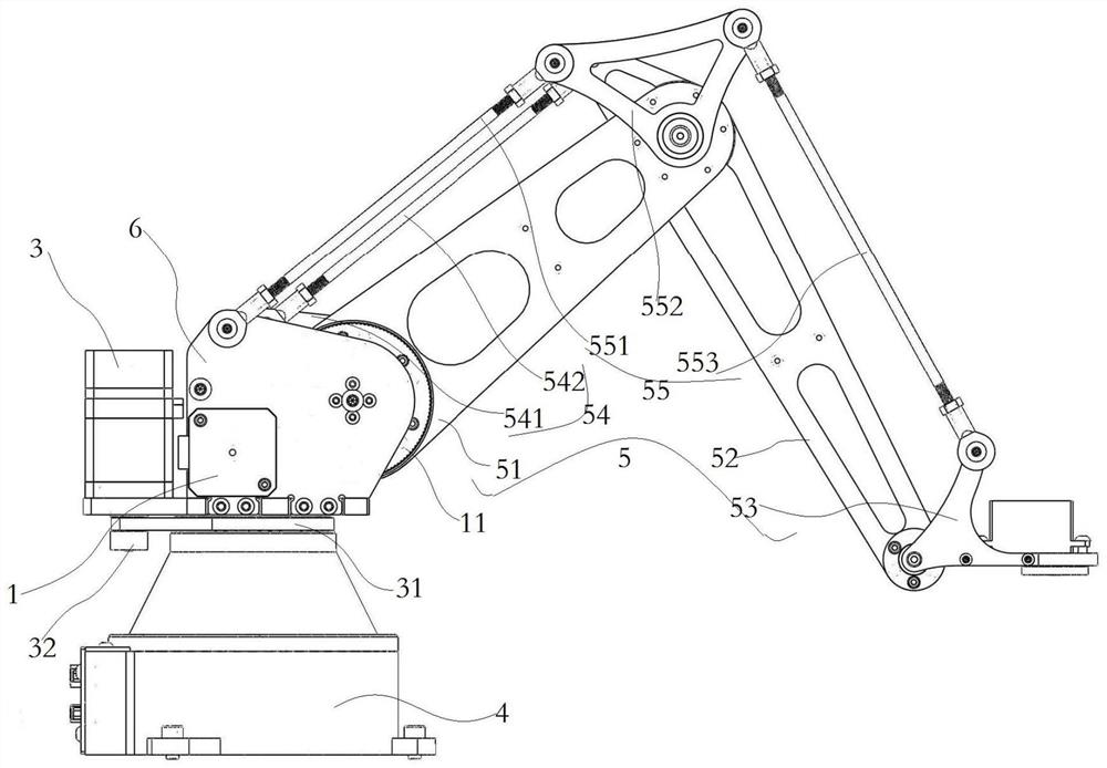
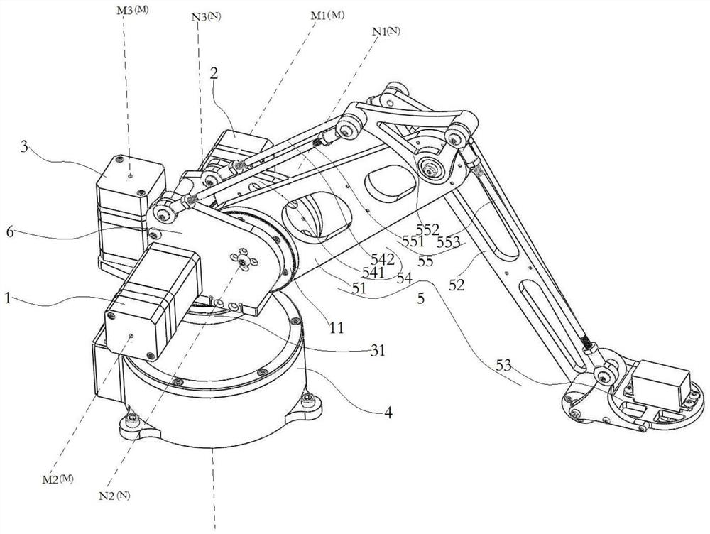
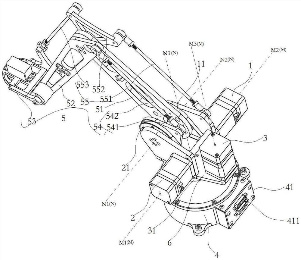
The invention discloses a synchronous belt transmission high-transmission-efficiency mechanical arm. The synchronous belt transmission high-transmission-efficiency mechanical arm comprises a driving machine body, the lower portion of the driving machine body is rotationally connected to a fixing base, the output end of the upper portion of the driving machine body is rotationally connected to a multi-section mechanical arm, the driving machine body is provided with three driving parts, each driving part comprises a driving part and a driven part, each of the driving part and the driven part has a rotational degree of freedom and corresponds to a first rotational axis and a second rotational axis respectively, second rotating axes of the driven parts of the two driving parts are coaxial, the second rotating axes are coaxial with the rotating axis where the multi-section mechanical arm is located and used for driving the multi-section mechanical arm to move, and the second rotating axis of the driven part of one of the driving parts is coaxial with the rotating axis of the driving machine body and is used for driving the driving machine body to rotate relative to the fixing base, so that high-absorption and reversible production line production of the mechanical arm can be realized, and the richness of the mechanical arm adapting to a production line is greatly improved.

Description

technical field [0001] The invention relates to the technical field of micro-manipulators for small-scale operations, in particular to a high-efficiency transmission-efficiency manipulator driven by a synchronous belt. Background technique [0002] The robotic arm is an automatic operating device that can imitate certain movement functions of the human hand and arm, and is used to grab, carry objects or operate tools according to a fixed program. The application in automatic production lines can better save energy and improve efficiency, and meet the development requirements of modern economy. [0003] The existing mechanical arm includes a fixed base and a first arm connected to the fixed base, a second arm and a driving part, and the driving part drives the swing between the first arm and the fixed base and the movement of the first arm or the second arm to realize Twice the speed and twice the travel. In addition, the current mechanical arm usually has multiple rotating...

Claims


Application Information

Patent Timeline
IPC IPC(8): B25J18/02
CPCB25J18/025
Inventor 梁林超杨鹏赵忠乾谢孙耘翰娄宇杰
Owner 杭州太希智能科技有限公司
Learn More